Sephacryl S-400 HR, 150 mL
Sephacryl High Resolution size exclusion chromatography resins allow fast and reproducible purification of proteins, polysaccharides, and other macromolecules by size exclusion chromatography at laboratory and industrial scale.
FAQ
Change Control Notifications and Regulatory Support Documentation are available for this product at the Regulatory Support Web Application, www.cytivalifesciences.com/rsf
After registering an account, you can start your subscription free of charge.
Packing procedures
BPG. Approximative values for the compression factor, slurry concentration and packing flow velocity
Recommended flow velocity in the table below are for packing the column.
| Column | Compression factor | Slurry concentration (%) | Bed height (cm) | Flow velocity (cm/h) Step 1 | Pressure (bar) Step 2 |
|---|---|---|---|---|---|
| BPG 100 | 1.15 | 50 - 70 | 30 - 60 | 100 | 0.7 |
| BPG 140 | 1.15 | 50 - 70 | 30 - 60 | 100 | 0.7 |
| BPG 200 | 1.15 | 50 - 70 | 30 - 60 | 100 | 0.7 |
| BPG 300 | 1.15 | 50 - 70 | 301 | 100 | 0.7 |
1 For higher beds than 30 cm, running two columns in series is to be recommended due to potential issues with bed stability.
Recommended flow velocites in the table below are for packing the column. The intervals are given in reverse order to indicate that the high flow velocity can be used for shorter beds whereas higher beds only allow lower flow velocity, due to the higher pressure drop across the bed.
| Column | Compression factor | Slurry concentration (%) | Bed height (cm) | Flow velocity (cm/h) Step 1 | Flow velocity (cm/h) Step 1 |
|---|---|---|---|---|---|
| XK 16 | 1.15 | 50 - 70 | 30 - 601 | 60 | 420 - 360 |
| XK 26 | 1.15 | 50 - 70 | 30 - 601 | 45 | 90 - 70 |
| XK 50 | 1.15 | 50 - 70 | 30 - 56 | 30 | 40 - 35 |
1 For 60 cm bed height pre-packed columns are available
| Column | Maximum operation pressure (bar) |
|---|---|
| HiScale | 20 |
| XK 16 | 5 |
| XK 26 | 5 |
| XK 50 | 3 |
| BPG 100 | 8 |
| BPG 140 | 6 |
| BPG 200 | 6 |
| BPG 300 | 4 |
| BPG 450 | 2.5 |
| BioProcess LPLC | 6 |
| BioProcess MPLC | 20 |
| Chromaflow 400 | 3 |
| Chromaflow 600 | 3 |
| Chromaflow 800 | 3 |
| Chromeflow 1000 | 3 |
| FineLINE Pilot 35 | 20 |
| FineLINE 70 | 20 |
| FineLINE 100 | 20 |
| FineLINE 200 | 20 |
| FineLINE 350 | 20 |
| Column | Compression factor | Slurry concentration (%) | Bed height (cm) |
|---|---|---|---|
| BioProcess LPLC column 400-1200 | 1.15 | 50 - 70 | 301 |
1 For higher beds than 30 cm, running two columns in series is to be recommended due to potential issues with bed stability
Two step constant flow packing.
Packing buffer: Tween
For more information regarding packing methods please read Appendix 1, Column and packing preparation in Gel Filtration Principles and Methods in Related Documents.
10 µm net stainless steel
| BPG 100 |
|---|
| 10 or 12 µm nets |
| Adaptor net 10 µm Code no: 18-1103-05 |
| Adaptor net 12 µm Code no: 18-1103-06 |
| End piece net 10 µm Code no: 18-0251-77 |
| End piece net 12 µm Code no: 18-1104-41 |
| BPG 140 |
| 10 or 12 µm nets |
| Adaptor net 10 µm Code no: 18-1113-03 |
| Adaptor net 12 µm Code no: 18-1113-05 |
| End piece net 10 µm Code no: 18-1113-02 |
| End piece net 12 µm Code no: 18-1113-04 |
| BPG 200 |
| 10 or 12 µm nets |
| Adaptor net 10 µm Code no: 18-0252-76 |
| Adaptor net 12 µm Code no: 18-1104-42 |
| End piece net 10 µm Code no: 18-0252-77 |
| End piece net 12 µm Code no: 18-1104-43 |
| BPG 300 |
| 10 or 12 µm nets |
| Adaptor net 10 µm Code no: 18-1012-55 |
| Adaptor net 12 µm Code no: 18-1104-44 |
| End piece net 10 µm Code no: 18-1012-35 |
| End piece net 12 µm Code no: 18-1104-45 |
One step compression packing
Packing buffer: 0.15 M NaCl
Column evaluation
The efficiency of a column depends on how well it is packed. A poorly packed column gives rise to uneven flow, resulting in zone broadening and reduced resolution. It is thus important to have a method by which the column can be tested before it is put into operation. Such a method should be simple, quantitative and should not introduce contaminating materials. It is also an advantage if the same method can be used to monitor column performance over its working life, so that it is easy to determine when the medium should be re-packed or replaced.
Avoid methods that use colored compounds such as Blue Dextran. They do not meet the above criteria and cannot be used with ion exchange and affinity chromatography media.
Experience has shown that the best method of expressing the efficiency of a column is in terms of the height equivalent to a theoretical plate, HETP, reduced plate number, h, and the peak asymmetry factor, As. These values can be determined easily by applying a NaCl or acetone solution, to the column (see below).
It is important that the column is properly equilibrated ( >2 column volumes) before evaluating the packing. Ideally, run three test runs to see whether the values are stable. If an initially poor result improves during a later test, the reason can be that the column was not properly equilibrated. To check that the bed is stable, run the column at 70% packing pressure for 20 hours and test it again.
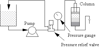
Note that pressure spikes may cause poor packing (cracking). If this happens, fit an air trap and a pressure relief valve between the pump and column. Locate the pressure relief valve between the air trap and the column.
Choice of test sample for columns
The most appropriate material for column testing is, of course, the sample that is to be run in the application, but this is not always practical or economical. As an alternative, a solution of either NaCl or acetone will give a good indication of the column packing quality. The eluate is monitored by measuring conductivity or UV absorption, and the resulting elution profile is used to calculate the HETP value.
The advantages of using NaCl are that it is readily available and can be used safely to test all columns. One disadvantage is that NaCl may interact with the medium matrix, especially ion exchanger matrices, and thus give erroneous results.
Acetone, in contrast, does not interact with the matrix and is detected by UV absorption at 280 nm. Alternatively, you can increase the running buffer concentration 10-fold and use it as test solution.
The figure below shows a UV trace for acetone in a typical BPG column application and gives calculated HETP and As values.

HETP calculation
The sample volume should be approximately 1% of the total bed volume and the concentration 1.0% v/v NaCl, or equivalent when using stronger buffer. Alternatively, use 1.0% v/v acetone. The flow velocity should be between 10 and 30 cm/h depending on the bead size of the chromatography medium. The high flow velocity could be used for small beads whereas large beads only allow low flow velocity. To avoid diluting the sample, apply it as close to the column inlet as possible. If an airtrap is included in the system, by-pass it during sample application to avoid back-mixing. Calculate the HETP value from the conductivity (or UV) curve as follows:
HETP, in its simplest terms, is expressed as:
HETP = L/N
where,
L = Bed height (cm)
N = Number of theoretical plates.
N is defined by the equation:
N = 5.54 (Ve /Wh)2
where,
Ve = Elution volume (ml)
Wh = Peak width at half height (ml)
Ve is measured as the volume passed through the column to the peak maximum.
Wh is measured as the peak width at half-peak height.
From the example in the figure, the HETP value can be calculated from the chromatogram as follows:
| Ve (ml) | Wh (ml) | N | N/m | HETP cm | |
| Acetone | 18800 | 900 | 2417 | 4203 | 0.024 |
Well-packed columns have low HETP values. However, it is only possible to compare columns that have been packed with the same type of media and that have been tested under identical conditions.
As a general rule-of-thumb, a good HETP value is approximately two to four times the mean bead diameter of the medium in question, provided that the sample does not interact with the medium.
In practice, the correlation between HETP and column performance can only be assessed by the column operator. Once this has been established, a standard can be set to judge the acceptability of a column packing.
For example, the column operator may know from experience that a column packed with Sephadex G-25 gel filtration medium with HETP values above 0.05 cm does not give the required separation. Consequently, the operator will set this value as the maximum permissible i.e. the minimum acceptable quality.
Reduced plate number
Definition of reduced plate number: h = HETP/dp
h = reduced plate number.
HETP = above described height equivalent to a theoretical plate.
dp = mean particle diameter of the chromatography medium beads.
The reduced plate number should be in the range of 2-4 times the mean particle diameter of the chromatography medium beads.
Peak asymmetry factor calculation
The peak asymmetry factor should be as close as possible to 1, and the shape of the peak should be as symmetrical as possible. This is usually the case for gel filtration media, but for certain ion exchange and affinity media, the shape may be asymmetrical due to interaction with the media. A change in peak shape is usually the first indication of column deterioration.
The peak asymmetry factor, As, is calculated from the graph above:
As = b/a
where,
a = distance from peak apex to 10% of the peak height on the ascending side of the peak
b = distance from peak apex to 10% of the peak height on the descending part of the peak
Note: Measuring HETP, h and As values is the best way to judge the condition of the packed column. A packed column can look good, but still need repacking for optimal performance. Always check the column after packing and regularly between runs to ensure best performance.
Two step packing: Constant flow packing followed by constant pressure packing.
Packing buffer large scale: 0.15 M NaCl
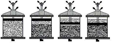
1. Pour some water (or packing buffer) into the column. Make sure that there is no air trapped under the bottom net. Leave about 2 cm of liquid in the column. Pour the gel slurry into the column.
2. Insert the adaptor and lower it to the surface of the slurry, making sure no air is trapped under the adaptor (1).
3. Seal the O-ring and lower the adaptor somewhat further into the slurry to fill the adaptor inlet with packing solution.
4. Packing is performed at a rather high constant flow rate until the predefined pressure is reached (2).Lower the adaptor to the bed surface (3).
5. This pressure is maintained for the rest of the packing. It is important that the total packing time is not exceeded, despite the appearance that the bed height may decrease further.
6. Close the bottom valve, stop the pump, disconnect the column inlet and lower the adaptor approximately 3 mm into the gel bed (4),without loosening the O-ring, while the packing solution is flushing the adaptor inlet. If any air should be trapped here it can be removed by pumping liquid upwards through the column (after inlet tubing and the bottom valve have been properly filled).
Depending on the final bed height, a packing tube may have to be mounted on the column tube during the first part of the packing to avoid exceeding the critical slurry concentration.
| XK 16/40 |
|---|
| 10 µm nets (5 pieces/pack) Code no: 18-8761-01 |
| XK 26/40 |
| 10 µm nets (5 pieces/pack) Code no: 18-8760-01 |
| XK 50/30 |
| 10 µm nets (5 pieces/pack) Code no: 18-8759-01 |