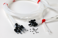
Inlet and Outlet Tubing Kit for ÄKTAcrossflow
Flow path schemes
The following flow diagram shows the positions of the components and tubing in the ÄKTAcrossflow liquid flow path.
For the inlet and outlet tubing kit, please refer to the red marked tubing.
Something went wrong - we were not able to load your agreed MSA pricing. Please try refreshing the page.
| Tubing | Length | I.d. (mm) | Material | Location | |
|---|---|---|---|---|---|
| From | To | ||||
| W1L | 2000 | 2.9 | ETFE | Transfer purge valve | Waste |
| TVB1L | 600 | 2.9 | ETFE | Air sensor | |
| TVB2L* | 1200 | 2.9 | ETFE | Transfer valve block 1 T-VB-in (port 2) | |
| TVB3L* | 1200 | 2.9 | ETFE | Transfer valve block 1 T-VB-in (port 3) | |
| TVB4L* | 1200 | 2.9 | ETFE | Transfer valve block 1 T-VB-in (port 4) | |
| TVB5L* | 1200 | 2.9 | ETFE | Transfer valve block 2 T-VB-in (port 5) | |
| TVB6L* | 1200 | 2.9 | ETFE | Transfer valve block 2 T-VB-in (port 6) | |
| TVB7L* | 1200 | 2.9 | ETFE | Transfer valve block 2 T-VB-in (port 7) | |
| TVB8L* | 1200 | 2.9 | ETFE | Transfer valve block 2 T-VB-in (port 8) | |
| RVB1L* | 600 | 2.9 | ETFE | Retentate valve block R-VB-Out (port 1 = pressure relief valve) | |
| RVB2S* | 600 | 1.7 | PVDF | Retentate valve block R-VB-Out (port 2) | |
| RVB3S* | 600 | 1.7 | PVDF | Permeate valve block P-VB-Out (port 3) | |
| PVB1L* | 2000 | 2.9 | ETFE | Permeate valve block P-VB-Out (port 1) | Waste |
| PVB2S* | 600 | 1.7 | PVDF | Permeate valve block P-VB-Out (port 2) | |
| PVB3S* | 600 | 1.7 | PVDF | Permeate valve block P-VB-Out (port 3 = pressure relief valve) | |
| *= Single nut | |||||
Something went wrong - we were not able to load your agreed MSA pricing. Please try refreshing the page.