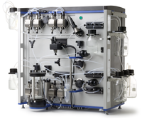
ÄKTAcrossflow
ÄKTAcrossflow has been discontinued. Service of ÄKTAcrossflow is available until 31 May 2026. After this date, we offer service upon availability of parts from our suppliers.
FAQ

Spare parts
Seals are considered as consumables and should be replaced annually or when needed. Please keep a set of each in your stock to prevent long downtime. For code numbers refer to the table below.
| # | Product Name | Product Code | Price | |
|---|---|---|---|---|
| 1 | Piston assembly, 400 ml, complete | 18116990 | 1,181.00 USD |
Add to cart
|
| 3 | Check valve, inner complete | 18116988 | 396.00 USD |
Add to cart
|
| 4 | Check valve, outer complete | 18116989 | 472.00 USD |
Add to cart
|
| 7 | Valve membrane | 11003143 | 249.00 USD |
Add to cart
|
| 8 | Rocker | 11003362 | 239.00 USD |
Add to cart
|
| 9 | O-ring 3 x 1 mm | 11002547 | 122.95 USD |
Add to cart
|
| 11 | O-RING KIT UV-M | 18368501 | 27.46 USD |
Add to cart
|
| # | Product Name | Product Code | Price | |
|---|---|---|---|---|
| 1 | Y-Connector, 5/16" Female | 18117059 | 526.00 USD |
Add to cart
|
| 2 | Luer Male - 5/16" Female | 11002707 | 60.03 USD |
Add to cart
|
| 3 | Union Luerlock Female/M6 Female | 18102712 | 63.55 USD |
Add to cart
|
| 4 | Connector 5/16" Female - M6 Male | 18112776 | 65.20 USD |
Add to cart
|
| 5 | Stop Plug 5/16" Male | 18111250 | 36.22 USD |
Add to cart
|
| 6 | Connector, 5/16" Female - 5/16" Female | 18117351 | 272.00 USD |
Add to cart
|
| 7 | Connector, 25 mm TC - UNF 5/16" Female | 18116922 | 191.48 USD |
Add to cart
|
| 8 | TC Gasket, 25 mm, i.d. 6.5 mm | 18116925 | 556.00 USD |
Add to cart
|
| 9 | Connector, 3 × UNF 5/16" Female | 28404769 | 187.33 USD |
Add to cart
|
| # | Product Name | Product Code | Price | |
|---|---|---|---|---|
| 1 | Check valve, inner complete | 18116988 | 396.00 USD |
Add to cart
|
| 1 | Check valve, outer complete | 18116989 | 472.00 USD |
Add to cart
|
| 1 | Piston assembly, 400 ml, complete | 18116990 | 1,181.00 USD |
Add to cart
|
| 2 | pH Calibration Kit for ÄKTAcrossflow | 11002716 | 220.00 USD |
Add to cart
|
| 2 | O-ring 5.3 x 2.4 mm | 18111860 | 76.73 USD |
Add to cart
|
| 2 | ÄKTApilot Dummy pH Electrode | 18116911 | 127.30 USD |
Add to cart
|
| 2 | Cell holder | 18117002 | 331.00 USD |
Add to cart
|
| 3 | Conductivity cell i.d. 2 | 18116900 | 967.00 USD |
Add to cart
|
| 3 | Cell holder air sensor/cond | 18117001 | 430.00 USD |
Add to cart
|
| 4 | UV Flow Cell 2 mm for ÄKTAcrossflow | 11003148 | 933.00 USD |
Add to cart
|
| 4 | Filter 254 nm | 18062001 | 826.00 USD |
Add to cart
|
| 4 | Filter 280 nm | 18062101 | 801.00 USD |
Add to cart
|
| 4 | Filter 214 nm | 18062201 | 935.00 USD |
Add to cart
|
| 4 | Filter 405 nm | 18062501 | 836.00 USD |
Add to cart
|
| 4 | Filter 436 nm | 18062601 | 836.00 USD |
Add to cart
|
| 4 | Hg optics with 254 and 280 nm filters | 28404223 | 7,232.00 USD |
Add to cart
|
| 4 | Zn optics with 214 nm filter | 28404224 | 7,232.00 USD |
Add to cart
|
| 4 | Hg lamp and housing complete | 28404225 | 2,239.00 USD |
Add to cart
|
| 4 | Zn lamp and housing complete | 28404226 | 2,936.00 USD |
Add to cart
|
| 5 | Air filter | 11002718 | 104.54 USD |
Add to cart
|
| 5 | Stirrer 30 × 6 for ÄKTAcrossflow | 11002721 | 65.20 USD |
Add to cart
|
| 5 | Stirrer 35 × 7 for ÄKTAcrossflow | 11002722 | 84.87 USD |
Add to cart
|
| 5 | Reservoir 1200 Complete for ÄKTAcrossflow | 11003116 | 6,760.00 USD |
Add to cart
|
| 5 | Reservoir 300 Complete for ÄKTAcrossflow | 11003146 | 2,951.00 USD |
Add to cart
|
| 5 | Reservoir Cleaning Kit for ÄKTAcrossflow | 11003386 | 275.00 USD |
Add to cart
|
| 6 | ÄKTApilot Air Sensor Cell 925 | 18116770 | 898.00 USD |
Add to cart
|
| 8 | Rocker | 11003362 | 239.00 USD |
Add to cart
|
| 9 | Valve complete | 11002670 | 1,703.00 USD |
Add to cart
|
| 10 | Valve | 11002671 | 1,594.00 USD |
Add to cart
|
| 11 | Pressure sensor, 2.5 MPa | 18116979 | 1,024.00 USD |
Add to cart
|
| 12 | Valve membrane | 11003143 | 249.00 USD |
Add to cart
|
| 13 | Connection block T-VB2 | 28405595 | 633.00 USD |
Add to cart
|
| 14 | Connection block P-VB | 28405597 | 633.00 USD |
Add to cart
|
| 15 | Flow Restrictor | 11002672 | 1,484.00 USD |
Add to cart
|
| 16 | Float, 300 ml | 11002677 | 647.00 USD |
Add to cart
|
| 17 | Float, 1200 ml | 11003288 | 941.00 USD |
Add to cart
|
| # | Product Name | Product Code | Price | |
|---|---|---|---|---|
| 1 | Tubing cutter, for PEEK, EFTE, and FEP tubing i.d. 0.25, 0.5, 0.75, 1 and 1.6 mm | 18111246 | 99.55 USD |
Add to cart
|
| 2 | Tool Kit for ÄKTAcrossflow | 11002714 | 343.00 USD |
Add to cart
|
| 5 | Stirrer 30 × 6 for ÄKTAcrossflow | 11002721 | 65.20 USD |
Add to cart
|
| 6 | pH Calibration Kit for ÄKTAcrossflow | 11002716 | 220.00 USD |
Add to cart
|
| 7 | Hollow Fiber Holder Block for ÄKTAcrossflow | 11002717 | 249.00 USD |
Add to cart
|
| 8 | Air filter | 11002718 | 104.54 USD |
Add to cart
|
| 10 | Screw lid kit | 11000410 | 49.68 USD |
Add to cart
|
| 11 | Tube Lock GL45 Cap for ÄKTAcrossflow | 11001252 | 148.00 USD |
Add to cart
|
| 12 | Connector, 3 × UNF 5/16" Female | 28404769 | 187.33 USD |
Add to cart
|
| 13 | O-ring 3 x 1 mm | 11002547 | 122.95 USD |
Add to cart
|
| 14 | Stop Plug 5/16" Male | 18111250 | 36.22 USD |
Add to cart
|
| 15 | Luer Lock Male/M6 Female for ÄKTAcrossflow | 11002643 | 397.00 USD |
Add to cart
|
| 16 | Union Luerlock Female/M6 Female | 18102712 | 63.55 USD |
Add to cart
|
| 17 | Connector 5/16" Female - M6 Male | 18112776 | 65.20 USD |
Add to cart
|
| 18 | Bottle Holder for ÄKTAcrossflow | 11002712 | 571.00 USD |
Add to cart
|
| 19 | Delivery Kit for ÄKTAcrossflow | 28916099 | 4,810.00 USD |
Add to cart
|
| # | Product Name | Product Code | Price | |
|---|---|---|---|---|
| 1 | Recirculation Tubing Kit with Large i.d. for ÄKTAcrossflow | 11003130 | 2,000.00 USD |
Add to cart
|
| 2 | Recirculation Tubing Kit with Small i.d. for ÄKTAcrossflow | 11003121 | 2,344.00 USD |
Add to cart
|
| 3 | Recirculation Manifold for ÄKTAcrossflow | 11003149 | 678.00 USD |
Add to cart
|
| 4 | Rinsing Tube Kit for ÄKTAcrossflow | 11003127 | 2,246.00 USD |
Add to cart
|
| 5 | Inlet and Outlet Tubing Kit for ÄKTAcrossflow | 11003128 | 3,900.00 USD |
Add to cart
|
| 6 | Transfer/Permeate Tubing Kit for ÄKTAcrossflow | 11003129 | 2,581.00 USD |
Add to cart
|
| 7 | Outlet Tubing Kit for ÄKTAcrossflow | 11003122 | 821.00 USD |
Add to cart
|
| 8 | Delivery Tubing Kit with Small i.d. for ÄKTAcrossflow | 11003123 | 11,500.00 USD |
Add to cart
|
| 9 | Filter Tubing Kit, i.d. 1.7 mm | 28916101 | 498.00 USD |
Add to cart
|
| 10 | Filter Tubing Kit, i.d. 2.9 mm | 28916102 | 510.00 USD |
Add to cart
|
| 11 | O-ring 3 x 1 mm | 11002547 | 122.95 USD |
Add to cart
|
Accessories
For installation onto systems that use Luer fitting please use UNF accessory kit.
| # | Product Name | Product Code | Price | |
|---|---|---|---|---|
| 2 | Stop Plug 5/16" Male | 18111250 | 36.22 USD |
Add to cart
|
| 3 | Filter Tubing Kit, i.d. 1.7 mm | 28916101 | 498.00 USD |
Add to cart
|
| 4 | O-ring 3 x 1 mm | 11002547 | 122.95 USD |
Add to cart
|
| 5 | Kvick UNF Accessory Kit | 11000671 | 80.73 USD |
Add to cart
|
| # | Product Name | Product Code | Price | |
|---|---|---|---|---|
| 2 | Stop Plug 5/16" Male | 18111250 | 36.22 USD |
Add to cart
|
| 3 | Filter Tubing Kit, i.d. 1.7 mm | 28916101 | 498.00 USD |
Add to cart
|
| 4 | O-ring 3 x 1 mm | 11002547 | 122.95 USD |
Add to cart
|
For installation onto systems that use Luer fitting please use UNF accessory kit.
| # | Product Name | Product Code | Price | |
|---|---|---|---|---|
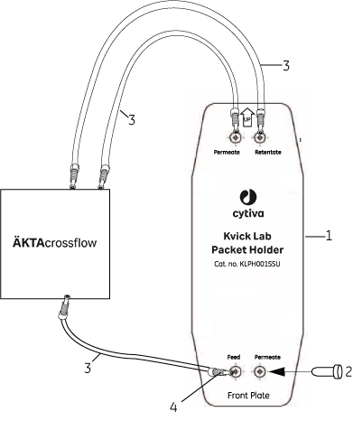
| 1 | Kvick Lab packet holder | 11000670 | 2,433.00 USD |
Add to cart
|
| 2 | Stop Plug 5/16" Male | 18111250 | 36.22 USD |
Add to cart
|
| 3 | Filter Tubing Kit, i.d. 1.7 mm | 28916101 | 498.00 USD |
Add to cart
|
| 3 | Filter Tubing Kit, i.d. 2.9 mm | 28916102 | 510.00 USD |
Add to cart
|
| 4 | O-ring 3 x 1 mm | 11002547 | 122.95 USD |
Add to cart
|
| 5 | Kvick UNF Accessory Kit | 11000671 | 80.73 USD |
Add to cart
|
Issue: This technical brief will describe the fittings and tubing required to physically connect a size 3M(A) or 4M(A) hollow fiber cartridge to the ÄKTAcrossflow system. The maximum feed flow rate on ÄKTAcrossflow is 600 ml/min.
Hollow Fiber Cartridge Housing Information:
 |
 |
| Housing 3M | Housing 4M |
| Permeate Ports = 6.4 mm (0.25 inch) hose barb | Permeate Ports = 9.5 mm (0.375 inch) hose barb |
| Feed/Retentate Ports = 25 mm TC | Feed/Retentate Ports =25 mm TC |
Fittings for Feed & Retentate Ports:
| Code no | Model no | Description | Qty/pack | Minimum Quality | Purpose/Comments |
|---|---|---|---|---|---|
| 18-1169-22 | - | Connector 25 mm - 5/16 female | 2 | 2 x Connector | Connect feed and retentate ports to system |
| 18-1169-25 | - | Gasket 25 mm TC i.d. 6.4 mm (0.25 inch) | 4 | 2 x Gasket | Seal connector to feed and retentate ports |
| or | |||||
| 56-4109-94 | KG4S | Gasket 25 mm TC i.d. 13 mm (0.5 inch) | 4 | 2 x Gasket | |
| 18-1169-18 | - | Clamp 25 mm TC | 4 | 2 x Clamp | Clamp connector and gaskets to feed and retentate ports |
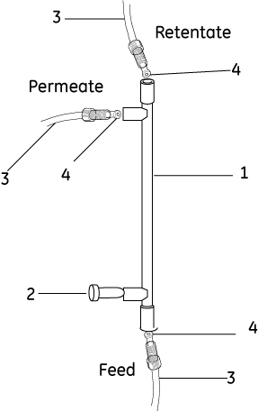
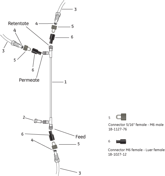
Fittings for Permeate Ports:
| Code no | Model no | Description | Qty/pack | Minimum Quality | Purpose/Comments |
|---|---|---|---|---|---|
| 18-1127-76* | - | Connector 5/16 female - M6 male | 3 | 1 x Fitting | Connect system permeate tubing to permeate port |
| 18-1169-43* | - | Connector M6 female - Luer male | 5 | 1 x Fitting | Bridge connection from system to cartridge |
| 56-4105-75 | RBFL-1 | Luer female - 3.1 mm (0.125 inch) barb | 10 | 1 x Fitting | Bridge connection from system to cartridge |
| 56-4106-17 | PTSL03-10 | Tubing i.d. 3.1 mm (0.125 inch) | L = 3.1 m | L = 0.25 m | Bridge connection, for Size 3 cartridge permeate port |
| 56-4106-18 | PTPM0&-10 | Tubing i.d. 6.4 mm (0.25 inch) | L 0 3.1 m | L 0 9.25 m | Bridge connection, for Size 3 or 4 cartridge permeate port |
| Not applicable | - | Cable Ties | 4 x Cable ties | Secure tubing |
*included in ÄKTAcrossflow accessory kit
Nominal Feed Flow Rates:
| Hosing Size | Nominal fiber i.d. (mm) | Shear Rate 2000 sec-1 (ml/min) | Shear Rate 4000 sec-1 (ml/min) | Shear Rate 8000 sec-1 (ml/min) | Shear Rate 16000 sec-1 (ml/min) |
|---|---|---|---|---|---|
| 3M | 0.5 | 63 | 125 | 251 | 502 |
| 1.0 | 153 | 306 | 613 | 1225 | |
| 4M | 0.5 | 293 | 586 | 1171 | 2342 |
| 1.0 | 589 | 1178 | 2356 | 4172 |
NOTE: The shaded area represents possible application on ÄKTAcrossflow. Each set of conditions must be tested with the particular feed stream and flux set point. For more information consult the Cytiva Operating Handbook, 18-1165-30, or contact your local representative.
Connection of Size 3 Hollow Fiber Cartridge to ÄKTAcrossflow:
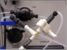
Feed & Retentate Ports: Place gasket between end port and connector 25 mm TC - 5/16 female, (18-1169-22). Secure with clamp.
Lower Permeate Port: Connect tubing i.d. 3.1 mm or 6.4 mm (56-4106-17, PTSL03-10 or 56-4106-18, PTPM06-10). Fold over tubing. Secure with cable ties.
Upper Permeate Port: Connect at least 2.5 cm tubing i.d. 3.1 mm or 6.4 m. Secure with cable ties.
Connect connector Luer female - 3.1 mm (0.125 inch) barb (56-4105-75, RBFL-1) >> M6 female - Luer male (11-0026-43) >> 5/16 female - M6 male (18-1127-76) >> system permeate connection.
Connection of Size 4 Hollow Fiber to ÄKTAcrossflow:
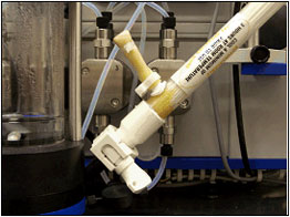
Feed & Retentate Ports: Place gasket between end port and connector 25 mm TC - 5/16 female, (18-1169-22). Secure with clamp.
Lower Permeate Port: Connect tubing i.d. 6.4 mm (56-4106-18, PTPM06-10). Fold over tubing. Secure with cable ties.
Upper Permeate Port: Connect at least 2.5 cm tubing i.d. 6.4 mm. Secure with cable ties.
Connect connector Luer female - 3.1 mm (0.125 inch) barb (56-4105-75, RBFL-1) >> M6 female - Luer male (11-0026-43) >> 5/16 female - M6 male (18-1127-76) >> system permeate connection.
NOTE: Snapper clamps are delivered with hollow fiber cartridges. They may be used to secure tubing to the lower and upper permeate port barbs. Use pliers to secure the fitting. Check for leaks before loading sample.
| # | Product Name | Product Code | Price | |
|---|---|---|---|---|
| 1 | Connector, 25 mm TC - UNF 5/16" Female | 18116922 | 191.48 USD |
Add to cart
|
| 2 | TC Gasket, 25 mm, i.d. 6.5 mm | 18116925 | 556.00 USD |
Add to cart
|
| 3 | Gasket 25 mm (0.5") TC i.d. 13 mm, silicone | 56410994 | 78.66 USD |
Add to cart
|
| 4 | ÄKTApilot Clamp, 25 mm TC | 18116918 | 351.00 USD |
Add to cart
|
| 5 | Connector 5/16" Female - M6 Male | 18112776 | 65.20 USD |
Add to cart
|
| 6 | Luer Lock Male/M6 Female for ÄKTAcrossflow | 11002643 | 397.00 USD |
Add to cart
|
| 7 | Connector Luer Female - 3.2 mm (0.125") Barb | 56410575 | 28.98 USD |
Add to cart
|
| 8 | Peristaltic Tubing, size 16, 3.1 m, i.d. 3.1 mm, silicone | 56410617 | 134.55 USD |
Add to cart
|
| 9 | Peristaltic Tubing, size 17, 3.1 m, i.d. 6.4 mm, bioprene | 56410618 | 153.18 USD |
Add to cart
|
For installation onto systems that use Luer fitting please use UNF accessory kit.
| # | Product Name | Product Code | Price | |
|---|---|---|---|---|
| 2 | Stop Plug 5/16" Male | 18111250 | 36.22 USD |
Add to cart
|
| 3 | Filter Tubing Kit, i.d. 2.9 mm | 28916102 | 510.00 USD |
Add to cart
|
| 4 | O-ring 3 x 1 mm | 11002547 | 122.95 USD |
Add to cart
|
| 5 | Kvick UNF Accessory Kit | 11000671 | 80.73 USD |
Add to cart
|
| # | Product Name | Product Code | Price | |
|---|---|---|---|---|
| 2 | Stop Plug 5/16" Male | 18111250 | 36.22 USD |
Add to cart
|
| 3 | Filter Tubing Kit, i.d. 1.7 mm | 28916101 | 498.00 USD |
Add to cart
|
| 3 | Filter Tubing Kit, i.d. 2.9 mm | 28916102 | 510.00 USD |
Add to cart
|
| 4 | O-ring 3 x 1 mm | 11002547 | 122.95 USD |
Add to cart
|
| # | Product Name | Product Code | Price | |
|---|---|---|---|---|
| 2 | Sample Holder for Two Tubes, for ÄKTAcrossflow | 11003125 | 514.00 USD |
Add to cart
|
| 3 | Bag Holder for ÄKTAcrossflow | 11003124 | 1,017.00 USD |
Add to cart
|
| 4 | Membrane Holder for ÄKTAcrossflow | 11003144 | 1,733.00 USD |
Add to cart
|
| 5 | Kvick Lab packet holder | 11000670 | 2,433.00 USD |
Add to cart
|
| 6 | Hollow Fiber Holder Block for ÄKTAcrossflow | 11002717 | 249.00 USD |
Add to cart
|
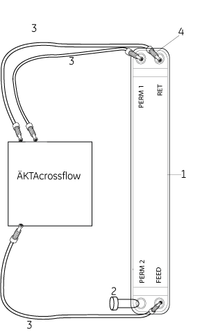
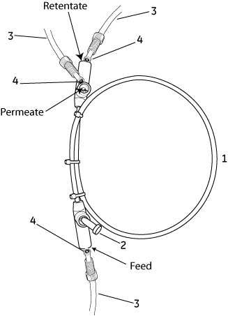
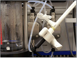
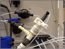
The figure shows a MidGee cross flow cartridge. The same connectors and tubing should be used for MidGee Hoop cross flow cartridges.
| # | Product Name | Product Code | Price | |
|---|---|---|---|---|
| 2 | Stop Plug Luer Female | 56410578 | 28.98 USD |
Add to cart
|
| 3 | Filter Tubing Kit, i.d. 1.7 mm | 28916101 | 498.00 USD |
Add to cart
|
| 4 | O-ring 3 x 1 mm | 11002547 | 122.95 USD |
Add to cart
|
| 5 | Connector 5/16" Female - M6 Male | 18112776 | 65.20 USD |
Add to cart
|
| 6 | Union Luerlock Female/M6 Female | 18102712 | 63.55 USD |
Add to cart
|
Troubleshooting
Find solutions to product related issues. For unlisted issues please contact local Cytiva service representation.
Unusual pump appearance
| Possible cause | Suggested remedy |
|---|---|
Air trapped in the pump head |
1.Check all connections for leakage. |
Blockage or partial blockage of flow path |
Flush through to clean blockage. If necessary replace tubing and connectors. |
Inlet and outlet check valves not functioning correctly |
There might be dirt in the check valves. Clean the valves according to instructions. |
Leaking connectors |
|
Piston damage |
If damaged, replace the piston according to instructions. It might also be necessary to replace piston assembly, glass tube and/or O-rings with new components. |
Piston leakage |
Replace the piston seal according to instructions. |
| Possible cause | Suggested remedy |
|---|---|
Connector incorrectly fitted or worn |
1.Check the connector and if necessary replace it. |
| Possible cause | Suggested remedy |
|---|---|
Piston, glass tube, liquid chamber or O-rings incorrectly fitted or worn |
Replace the piston assembly glass tube and/or O-rings in the pump head according to instructions. |
| Possible cause | Suggested remedy |
|---|---|
Spring is damaged |
Disassemble the pump head and examine the piston spring. Replace the piston assembly if necessary. All according to instructions. |
Spring is corroded |
Disassemble pump cylinder and examine the piston spring. If the spring is corroded, check if the piston, glass tube and O-rings are intact. Replace if necessary. All according to instructions. Preventive actions: Make sure the piston rinsing system is always used when working with aqueous buffers with high salt concentration |
Piston is damaged |
If damaged, replace the piston according to instructions. It might also be necessary to replace piston assembly, glass tube and/or O-rings with new components |
Air sensor issues
| Possible cause | Suggested remedy |
|---|---|
Connector incorrectly fitted or worn |
Tighten or replace the connector if necessary. |
| Possible cause | Suggested remedy |
|---|---|
Dirt in the flow path |
Clean the air sensor according to instructions. Change the air sensor according to instructions in ÄKTAcrossflow Instrument Handbook. |
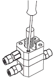
Membrane valves unusual appearance
| Possible cause | Suggested remedy |
|---|---|
Connector incorrectly fitted or worn |
Tighten or replace the connector if necessary. |
| Possible cause | Suggested remedy |
|---|---|
Dirt in the flow path |
Clean the valve according to instructions. Change the valve membrane according to instructions in ÄKTAcrossflow Instrument Handbook. |
| Possible cause | Suggested remedy |
|---|---|
Valve membrane is worn or damaged |
Change valve membrane according to instructions in ÄKTAcrossflow Instrument Handbook. |
| Possible cause | Suggested remedy |
|---|---|
Valve membrane is damaged |
Change valve membrane according to instructions in ÄKTAcrossflow Instrument Handbook. |
UV curve issues
| Possible cause | Suggested remedy |
|---|---|
Dirt and residues in the flow path from previous run |
Clean the system according to instructions. Also clean the cassette/cartridge according to instructions. |
| Possible cause | Suggested remedy |
|---|---|
Contaminated UV-cell |
Clean the UV-cell according to instructions |
Damaged membrane |
Check if the signal is still noisy in water. |
Impure buffer |
Check if the signal is still noisy in water. |
Incorrect cable connections |
Check that the UV cell is properly attached to the panel. |
Incorrect connections of the UV-cell optical fibers |
Check the connections of the UV-cell optical fibers. Replace if necessary |
No flow through UV cell |
Check for appropriate control mode. |
Pressure sensor unusual appearance
| Possible cause | Suggested remedy |
|---|---|
Connector incorrectly fitted or worn |
Tighten or replace the connector if necessary. |
| Possible cause | Suggested remedy |
|---|---|
Dirt in the flow path |
Clean the pressure sensor according to instructions. Change the pressure sensor according to instructions. See ÄKTAcrossflow Instrument Handbook. |
General Advice for automated filtration systems
For Automated Filtration Systems (ÄKTAcrossflow and UniFlux), here are a few general items to check while troubleshooting any problem. Please make sure that:
Correct system has been selected in UNICORN System Control
Correct Unicorn System Strategy and
All tubing has been properly connected
All connectors are free from leakage
No tubing is folded or twisted
Online filter, if used, is changed on a regular basis
Correct buffers are used for the chosen columns and proteins
All inlet tubing has been immersed in correct buffer solutions
Enough buffer has been prepared
Buffers have been equilibrated to the environment temperature
Suitable Membrane pore size has been selected for the target proteins
New filters have been have been cleaned and prepared according to instructions
Previously used filters have been have been cleaned and prepared according to instructions
Samples volume and system working volume have been used in calculations of concentration factor and diafiltration beforehand
Process settings of Membrane Capacity, Flux, Shear (or volumetric cross flow rate) have been properly applied for both sample characteristics and membrane pore size or NMWC designation.
The fraction collector has been filled with appropriate number of microtiter plates or tubes
Appropriate arrangement for waste handling has been prepared
Manual valves to process feed tank (with UniFlux System processes) are open
Conductivity curve issues
| Possible cause | Suggested remedy |
|---|---|
Calibration of the conductivity cell is incorrect |
Calibrate the conductivity cell according to instructions. |
Calibration solution 1.00 M NaCl not correctly prepared |
Prepare a new calibration solution and re-calibrate the conductivity cell according to instructions. |
| Possible cause | Suggested remedy |
|---|---|
Contaminated conductivity flow cell |
Clean the flow cell according to instructions |
Ambient temperature may have decreased |
The conductivity of the solution changes with temperature. Use a temperature compensation factor according to instructions. |
Buffer might loose it's characteristics over time |
Change buffer |
| Possible cause | Suggested remedy |
|---|---|
Cassette/cartridge is not equilibrated |
Equilibrated the cassette/cartridge. If necessary clean the cassette/cartridge |
Incorrect temperature compensation factor might be in use. |
Please adjust the temperature compensation factor according to instructions |
Membrane valves doesn't operate correctly |
Check the valve and replace if necessary according to instructions |
Pump doesn’t operate properly |
Check the operation of the pump according to instructions |
Temperature sensor might not be calibrated. |
Please calibrate the temperature sensor according to instructions. |
| Possible cause | Suggested remedy |
|---|---|
Cassette/cartridge is not equilibrated |
Equilibrated the cassette/cartridge. If necessary clean the cassette/cartridge |
Contaminated conductivity flow cell |
Clean the flow cell according to instructions |
Leaking tubing connections |
Tighten the connectors. If necessary replace the connector. |
No flow through the cell |
Check for appropriate control mode. |
System pump doesn't operate properly |
Check the operation of the pump according to instructions |
Pressure curve issues
| Possible cause | Suggested remedy |
|---|---|
Air bubbles passing through or trapped in the pump |
Check all connections for leakage. Check that there is sufficient liquid present in the reservoirs. |
Blockage or partial blockage of flow path |
Flush through to clean blockage. If necessary replace tubing and/or connectors. |
Inlet and outlet check valves not functioning correctly |
There might be dirt in the check valves. Clean the valves according to instructions |
Piston assembly is leaking |
Replace the piston assembly, glass tube and/or O-rings in the pump head according to instructions. |
Maintenance
Maintenance instructions and procedures.
Maintenance for ÄKTAcrossflow Filter Systems
Regular maintenance is important for safe and trouble-free operation of your instrument.
The user should perform daily and monthly maintenance. Preventive maintenance should be performed on a yearly basis by qualified service personnel.
For maintenance of a specific component, carefully read the component manual and follow the instructions. To avoid personal injury when performing maintenance on the ÄKTAcrossflow instrument, follow the instructions below.
This web site provides instructions for user maintenance and for replacing spare parts.
To get a service contract please contact your local Cytiva technical support representative.
Warning! Notice! Caution!

Cleaning. Keep the instrument dry and clean. Wipe regularly with a soft damp tissue and, if necessary, a mild cleaning agent. Let the instrument dry completely before use.
When using hazardous chemicals, take all suitable protective measures, such as wearing protective glasses and gloves resistant to the chemicals used. Follow local regulations and instructions for safe operation and maintenance of the system.

Disconnect power. Always disconnect power from the instrument before replacing any component on the instrument, unless stated otherwise in the user documentation.
Do not perform any type of maintenance work while the system is powered electrically or when the piping system is pressurized. Note that the piping system can be pressurized even when the system is closed down.
Hazardous chemicals during maintenance. When using hazardous chemicals for system or column cleaning, wash the system or columns with a neutral solution in the last phase or step.

Fire hazard. Follow instructions in the User Manual for correct installation of a new UV-lamp. If the lamp is not installed properly it may be overheated and cause a fire hazard.
Electrical shock hazard. All repairs should be done by service personnel authorized by Cytiva. Do not open any covers or replace parts unless specifically stated in the user documentation.
Cleaning
Make sure that the piping system is completely leakage free before performing any CIP on the system.
Hazardous chemicals during maintenance. When using hazardous chemicals for system or column cleaning, wash the system or columns with a neutral solution in the last phase or step.
NaOH is corrosive and therefore dangerous to health. When using hazardous chemicals, avoid spillage and wear protective glasses and other suitable personal protective equipment.
Disassembly and assembly of components and consumables
After assembly, the piping system must be tested for leakage at maximum pressure for continued protection against injury risks due to fluid jets, burst pipes or explosive atmosphere.
Before disassembly, check that there is no pressure in the piping system.
Disconnect power. Always disconnect power from the instrument before replacing any component on the instrument, unless stated otherwise in the user documentation.
Replacement of fuses
For continued protection from fire hazard, replace only with same type and rating of fuse.
Disconnect power. Always disconnect power from the instrument before replacing any component on the instrument, unless stated otherwise in the user documentation.
"Change me"
Maintenance operations should be performed by the user at regular intervals
Change rinsing solution. Use 10 mM NaOH in 20% ethanol as rinsing solution.
If the volume of rinsing solution in the storage bottles has increased, it can be an indication of internal pump leakage. Replace the piston assembly, glass tube, and/or O-rings in the pump head. Run the Replacing feed pump P-984 and transfer/permeate pump P-982 procedure found in the Detailed procedures list below.
If the volume of rinsing solution in the storage bottle has decreased significantly, check that the rinsing system connectors are mounted properly.
If the rinsing system connectors are not leading, the piston, glass tube, and/or O-rings might be damaged. Replace according to instructions. Run the Replacing feed pump P-984 and transfer/permeate pump P-982 procedure found in the Detailed procedures list below.
Calibrate the pH electrode. Replace the pH electrode if necessary. Run the Calibrating the pH electrode and Replacing the pH electrode procedure found in the Detailed procedures list below.
Feed pump Transfer pump Permeate pump- Check for leakage. If there are signs of liquid leaking between a pump head and the system panel, or increased or decreased volume of rinsing solution, replace the piston assembly, glass tube, and/or O-rings in the pump head. Run the Replacing feed pump P-984 and transfer/permeate pump P-982 procedure found in the Detailed procedures list below.
- Remove air bubbles. When changing buffer, it is important to remove trapped air. Prime the pump. Run the Manual priming of the system procedure found in the Detailed procedures list below.
System
- Clean the cover. Run the Cleaning the system procedure found in the Detailed procedures list below.
- Inspect the system for liquid leakage. Check that tubing and connectors are not damaged. Replace if necessary.
- Wash the system flow path. Avoid leaving the system filled with buffer overnight. Wash the flow path with distilled water. If leaving the system for a few days use 20% ethanol. Make sure that all tubing and flow paths used are rinsed. Run the Cleaning the system procedure found in the Detailed procedures list below.
- Check fan operation. Check that cooling air flows through the system, exiting at the right-hand side of the instrument.
Check UV lamp run time.
Checking UV lamp run time
In the System Control module, select System:Maintenance... to check the UV lamp run time.
- The lifetime of a Hg lamp at 254 nm in room temperature is typically 7000 hours (in cold room, typically 2000 h).
- The lifetime of a Hg lamp at 280 nm in room temperature is typically 3500 hours.
When necessary, replace the lamp according to section Changing lamp assembly, or contact Cytiva for lamp replacement.
Clean the conductivity cell.
Cleaning the conductivity cell
|
WARNING! NaOH is corrosive and therefore dangerous to health. Avoid spillage and wear protective glasses. |
If the conductivity measurements are not comparable to previous results, the electrodes in the conductivity cell might be contaminated and require cleaning.
To clean the cell:
- Pump 15 ml of 1 M NaOH at 10 ml/min through the cell either by using a pump or a syringe.
- Leave it for 15 minutes.
- Rinse thoroughly with 500 ml de-ionized water.
Note: If the cell is totally blocked, the blockage can be broken by carefully using a needle or a piece of string.
Clean the UV flow cell. Clean the cell to ensure proper UV monitoring.
Cleaning the UV flow cell off-line
- Flush a small amount of distilled water through the cell.
- Connect a 10 ml syringe to the inlet of the cell and squirt distilled water through the cell in small amount then fill the syringe with a 10% surface active detergent solution like Decon 90TM, Deconex 11TM, RBS 25 or equivalent, and squirt five times.
- After five squirts, leave the detergent solution in the cell for at least 20 minutes.
- Pump the remaining detergent solution through the cell.
- Rinse the syringe and flush the cell with distilled water (30 ml).
Replace the stirrer bar
Replace the O-rings.
Feed pump Transfer pump Permeate pumpReplace piston. Replace glass tube. Replace O-rings. Clean or replace the inlet and outlet check valves. Clean the rinsing system check valve.
Run the Replacing feed pump P-984 and transfer/permeate pump P-982 procedure found in the Detailed procedures list below.
pH electrode
Clean the pH electrode. Run the Cleaning the pH electrode procedure found in the Detailed procedures list below.
Valve blocksReplace the membrane. Replace the rockers. Run the Replace membrane valve block procedure found in the Detailed procedures list below.
Conductivity cellClean the conductivity cell.
Cleaning the conductivity cell
| WARNING! NaOH is corrosive and therefore dangerous to health. Avoid spillage and wear protective glasses. |
If the conductivity measurements are not comparable to previous results, the electrodes in the conductivity cell might be contaminated and require cleaning.
To clean the cell:
- Pump 15 ml of 1 M NaOH at 10 ml/min through the cell either by using a pump or a syringe.
- Leave it for 15 minutes.
- Rinse thoroughly with 500 ml de-ionized water.
Note: If the cell is totally blocked, the blockage can be broken by carefully using a needle or a piece of string.
UV flow cell
Clean the UV flow cell. Clean the cell to ensure proper UV monitoring.
Cleaning the UV flow cell off-line
- Flush a small amount of distilled water through the cell.
- Connect a 10 ml syringe to the inlet of the cell and squirt distilled water through the cell in small amount then fill the syringe with a 10% surface active detergent solution like Decon 90TM, Deconex 11TM, RBS 25 or equivalent, and squirt five times.
- After five squirts, leave the detergent solution in the cell for at least 20 minutes.
- Pump the remaining detergent solution through the cell.
- Rinse the syringe and flush the cell with distilled water (30 ml).
Detailed procedures for maintenance operations
When replacing the wetted parts of a valve block, the connection block as well as all membranes should be replaced. At normal user maintenance, only the membranes need to be replaced.
Spare parts and tools required:
- Connection block (see Ordering information for code no.)
- Valve membrane (see Ordering information for code no.)
- 7 mm wrench
Removing the connection block and membranes
- Flush the valve block thoroughly with distilled water.
- Disconnect all tubing from the valve block.
- Disconnect the Ethernet cable between the instrument and the computer. The Power indicator on the front panel starts flashing slowly, which indicates that the communication between the computer and the instrument unit is broken. All valves move to closed position.
- Remove the six attachment screws using the wrench.
- Carefully loosen the connection block.
- Pull out and discard the old membranes. Be careful not to scratch the mechanical housing of the valve!
Membrane valve block, exploded view
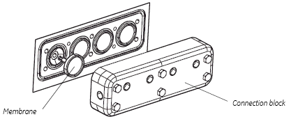
Installing the connection block and membranes:
- Fit the new membranes into position.
- Carefully fasten the connection block using the attachment screws.
- Connect the tubing.
- Connect the Ethernet cable between the instrument and the computer.
- When the connection between the computer and the instrument unit is established, the valves take up their normal positions in End mode.
Spare parts and tools required:
– pH electrode, ÄKTAcrossflow
– Cell holder, pH (see Ordering information for code nos.)
– Phillips screwdriver
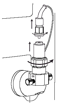
Replacing the pH electrode
1. Switch off the system with the mains power switch.
2. Unscrew the cable connector at the top of the old pH electrode.
3. Unscrew the locking nut that secures the pH electrode.
4. Remove the pH electrode.
5. Unpack the new pH electrode.
6. Remove the end cover. Make sure that it is not broken or dry.
7. Before using the electrode, immerse the glass tip in a pH 4 buffer solution for 30 minutes.
8. Carefully insert the electrode in the cell holder. Tighten the locking nut by hand to secure the electrode.
9. Fit the signal cable to the top of the pH electrode.
Replacing the cell holder
- Flush the cell holder with distilled water.
- Disconnect the tubing.
- Disconnect the signal cable from the top of the pH electrode (if used).
- Move the pH electrode or the dummy electrode to the new cell holder.
- Remove the ground wire from the cell holder using the Phillips screwdriver.
- Release the old cell holder from the panel by turning it a quarter of a turn.
- Fasten the new cell holder on the panel.
- Connect the tubing.
- Connect the signal cable to the pH electrode (if used).
|
WARNING! NaOH is corrosive and therefore dangerous to health. Avoid spillage and wear protective glasses. |
If the conductivity measurements are not comparable to previous results, the electrodes in the conductivity cell might be contaminated and require cleaning.
To clean the cell:
- Pump 15 ml of 1 M NaOH at 10 ml/min through the cell either by using a pump or a syringe.
- Leave it for 15 minutes.
- Rinse thoroughly with 500 ml de-ionized water.
Note: If the cell is totally blocked, the blockage can be broken by carefully using a needle or a piece of string.
The Hg optics with 254 and 280 nm filters and the Zn optics with the 214 nm filter
are delivered with filters installed. If other filters are to be used, install the new
filters as described in section Installing optical filters (optional).
Installing optical filters (optional)
The Hg optics with 254 and 280 nm filters and the Zn optics with the 214 nm filter
are delivered with filters installed. If other filters are to be used, install them as
follows:
- If the Zn lamp is attached, remove the lamp housing as described in section Changing the UV lamp.
- Remove the four screws in the filter housing. Separate the filter housing from the detector housing.
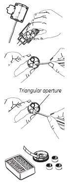
- Carefully remove the filter wheel from the filter housing.
- If necessary, remove the filter(s) from the filter wheel by pressing it (them) out, e.g. with a small screwdriver.
Note: Filters are sensitive optical components. Never touch the optical surfaces or expose them to temperatures above 60 °C. Clean them with dry lens cleaning tissue and store them, when not in use, in the box in which they were supplied. Heavy contamination may be removed by using a lens tissue dipped in ethanol. - Insert the filter(s) of choice into the filter wheel (maximum 3 filters) with the correct orientation (the mirror side facing upwards) and position over one of the three triangular apertures. The filters snap in by pressing them quite firmly. Do not touch the filter surface.
- Remove the circular plastic band showing the wavelength(s).
- Remove labels from the band if necessary.
- Place the correct labels on the band with the label designation facing outwards. Ensure that the label position corresponds to the filter position, i.e. the label should be placed opposite the filter.
- Reassemble the circular plastic band with the filter wheel peg fitting into the band notch.
- Check that all filters are clean. Insert the filter wheel back into the filter housing.
Note: The filter wheel can only be placed in the correct position. - Reassemble the filter housing with the detector housing by fastening the four screws.

|
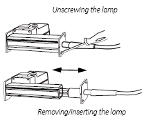
WARNING! The module uses high intensity ultra-violet light. Do not remove the UV lamp while the instrument is running. Before changing a UV lamp, ensure that the mains power is turned off to prevent injury to eyes. If the mercury lamp is broken, make sure that all mercury is removed and disposed of according to national and local environmental regulations. |
- Remove the two screws on the lamp housing end plate that is attached to the power cable.
- Carefully slide the lamp out of the lamp housing.
- Without touching the lamp glass, insert the new lamp into the lamp housing and secure the end plate with the two screws.
|
WARNING! Incorrectly fitted tubing might loosen, causing a jet of liquid to spray out. This is especially dangerous if hazardous chemicals are in use. Connect the tubing by first inserting the tubing fully, then tightening the connector finger tight. |
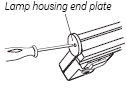
- Use a Phillips screwdriver to detach the end plate by removing one and loosening the other of the two holding screws on the lamp housing to be removed.
- Slide the lamp housing off the filter housing.
- Detach the end plate, as in step 1 above, from the lamp housing to be fitted to the optical unit.
- Slide the lamp housing onto the filter housing. The lamp and signal cables should be on the same side. As you slide the lamp housing into position, depress the two pressure pads on the filter housing in sequence to facilitate the installation.
- Refit the lamp housing end plate.
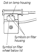
- Slide the lamp housing firmly into place. There will be a faint click when the housing is positioned correctly. The Hg lamp housing can take up two positions, one for 280 nm, marked by
on the filter housing, and the other marked by
for all other wavelengths. The Zn lamp housing has only one position.
- Set the wavelength to be used by selecting lamp position (indicated by a dot on the lamp housing) in combination with the appropriate filter, i.e. the dot on the lamp housing should be adjacent to the symbol on the filter housing corresponding to the symbol on the filter wheel for the filter to be used. A click will indicate that the filter is inposition.
Note: In UNICORN, the wavelength used set in the method notes.
When replacing the wetted parts of a valve block, the connection block as well as all rockers should be replaced. During normal user maintenance, only the rockers need to be replaced.
Spare parts and tools required:
- Connection block (see Ordering information for code no.)
- Rocker (see Ordering information for code no.)
- 7 mm wrench
Removing the connection block and rockers
- Flush the valve block thoroughly with distilled water.
- Disconnect all tubing from the valve block.
- Disconnect the Ethernet cable between the instrument and the computer. The Power indicator on the front panel starts flashing slowly, which indicates that the communication between the computer and the instrument unit is broken. All valves move to closed position.
- Remove the six attachment screws using the wrench.
- Carefully loosen the connection block.
- Pull out and discard the old rockers. Be careful not to scratch the mechanical housing of the valve!
Rocker valve block, exploded view
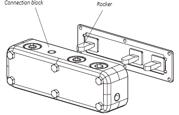
Installing the connection block and rockers:
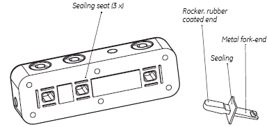
- Insert the rubber coated end of the new rockers into the connection block. Check that the rectangular sealing fits correctly to its counterpart.
- Insert the fork-shaped metal end of the rocker into the slit on the instrument front panel. Check that the metal fork-end is mated to the slit in the stepper-motor rod inside the front panel of the instrument, see figure below.
- Attach the connection block to the front panel by tightening the six attachment screws.
- Re-connect the tubing.
- Connect the Ethernet cable between the instrument and the computer.
- When the connection between the computer and the instrument unit is established, the valves take up their normal positions in End mode.
If there are signs of liquid leaking between the pump head and the housing side panel, or the volume of the rinsing solution has increased or decreased, replace the piston assembly, liquid chamber and/or glass tube including O-rings of the leaking pump head.
Other typical symptoms of a damaged piston are observed as excessive piston wear, unstable pressure, a reduction in the flow or, in some cases, noise as the piston moves. The piston should be removed, examined for damage or salt precipitation and then replaced with a new piston if necessary.
If a damaged piston has been in operation, the glass tube might be damaged as well and should also be replaced.
If cleaning of a faulty check valve does not improve its performance, it should be replaced.
|
CAUTION! Do not disassemble the pump head unless there is good reason to believe that there is an internal leakage. Always make sure that sufficient spare components are available before attempting to replace a spare part. |
Note: The power must be switched OFF when removing and refitting the pump heads.
Note: Always replace the piston on both pump heads on the P-982 pump, and on all four pump heads on the P-984 pump at the same time.
Spare parts and tools required:
Seal kit containing (see spare parts for code no):
- Piston assembly
- Seal kit (includes O-rings and sealings)
- Check valve, inner
- Check valve, outer
- Glass tube
- 3 mm Allen key
- 16 mm wrench
- 16 mm torque wrench
- Screwdriver, flat-headed, with torque adapter
Note: Before disassembling the pump heads, move all input buffer bottles below the level of the pump heads to prevent siphoning.
|
CAUTION! Read the following instructions carefully. Some individual parts of the pump head can be assembled incorrectly. Check the orientation of each part before continuing with the next instruction. |
- Switch off the system with the mains power switch on the rear panel of the instrument.
- Remove the tubing connectors on the inlet and outlet check valves.
- Remove the rinsing system tubing.
- If the check valves are also to be checked/replaced, use the wrench to loosen the valves slightly. Do not remove them completely.
- Using the Allen key, unscrew the two Allen screws locking the pump head in position. Loosen the screws half a turn on each screw at a time while pushing firmly on the front face of the pump head to compensate for the pressure of the piston return spring.
- Carefully pull out the pump head and place it face down on the bench.
- Using the flat-headed screwdriver, remove the two screws locking the piston assembly in position. Pull out the piston assembly.
- Gently pull the glass tube off the piston.
- Inspect the glass tube using a magnifying glass. Replace with a new glass tube if any scratches or cracks are found.
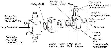
Pump head, exploded view
- Inspect the piston, piston rod and return spring for signs of damage. If damaged, the piston assembly should be replaced.
- Wipe the piston with a clean cloth. Inspect the piston with a magnifying glass for scratches. Replace the piston assembly if any scratches or cracks are found.
- If salt solutions have been used, the piston rod or spring may be slightly corroded. This corrosion can be removed with a rubber eraser. If it cannot be wiped or rubbed clean, scrape off any deposits with a scalpel or a razor blade.
 |
 |
 |
Replacing the O-rings
- Carefully remove and discard the old rinse chamber O-ring.
- Insert a new O-ring (thin).
- Lift off the liquid chamber.
- Carefully remove and discard the old pump head front O-ring.
- Insert a new O-ring (thick).
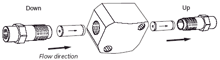
Replacing the outer check valves
- Unscrew the two loose check valves. Note the direction of the pistons inside the valves. The flow always enters a valve tube through the round hole and exits through the triangular hole.
- Inspect the nuts and the valve tubes for dirt or damage.
- Replace with a new check valve if any dirt or damage is found and cleaning does not improve the performance of the old check valve. For more information about the cleaning of the check valves, run the Cleaning the inlet and outlet check valves procedure found below.
- Tighten the new check valve using the torque wrench. See Pump head, exploded view for the tightening torque value.
CAUTION! Handle the check valves with care when they have been removed from the pump heads to prevent loss of any internal components.
Replacing the inner check valve
- Use the two wrenches to remove the metal nut of the check valve from the adapter. Note the direction of the valve tube inside the adapter; the round hole faces the rinse chamber.
- Use a wrench to remove the adapter from the rinse chamber.
- Inspect the nuts for dirt and damage. Replace the check valve and/or the adapter if required.
- Tighten the new check valve and/or adapter using the torque wrench. See Pump head, exploded view for the tightening torque values.
|
CAUTION! Over-tightening might damage threads. Use a torque wrench to tighten the components |
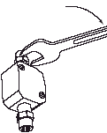
Installing the pump head
- Turn the pump head so that the inner check valve is facing upwards and the drainage hole downwards. Mount the complete pump head over the locating pins on the front panel.
- Press firmly on the pump head front and use the Allen key to fit and tighten the two retaining screws alternately a little at a time.
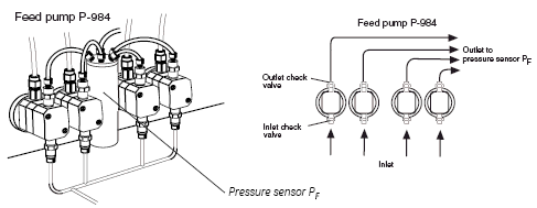
Connecting the tubing
|
|
- Connect the outlet tubing between the outlet check valve and the sensor PF.
- Connect the rinsing system tubing.
- Connect the inlet tubing to the inlet check valve.
- The pump is ready to be primed. Run the Manual priming of the system procedure found below
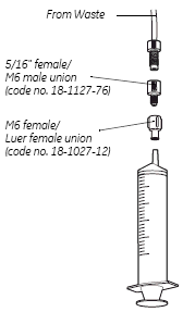
To prime the transfer pump and inlet tubing manually:
- Fill a flask with distilled water and immerse the appropriate valve block (T-VB-In) inlet tubing in the water.
- Connect a 5/16" connector to the waste tubing.
- Connect a 5/16" female/M6 male union to the tubing.
- Connect a M6 female/Luer female union to the first union.
- Fit an empty male Luer syringe (> 25 ml) to the Luer union.
- In the System Control module, select Manual:Transfer:TransferValveblocks, and then select TransferPurgeValve Waste.
- Open the appropriate inlet valve and Waste.
- Use the syringe to draw water through the inlet tubing and pump until it starts to enter the syringe.
A good laboratory routine is to calibrate the pH electrode at least once a day, when the electrode is replaced or if the ambient temperature is changed. The pH electrode is calibrated using standard buffer solutions in a two point calibration. The two buffer solutions may have any pH value as long as the difference between them is at least 1 pH unit, and the expected pH during the run is within this interval.
Note: The pH-calibration kit can be found in the Accessory box.
Calibrating with the electrode outside the cell holder
When calibrating the electrode out of the cell holder and changing from one buffer to another, rinse the electrode tip with distilled water and dab it carefully with a soft tissue to absorb the remaining water. Do NOT wipe the electrode as this may charge it and give unstable readings.
- In the System Control module, select System:Calibrate.
- Select pH from the Monitor pop-up menu in the Calibration window.
- Prepare two reference buffer solutions, the first normally pH 7.0. The difference in pH value between them must be at least 1 pH unit. The expected pH value during the run should be within this interval.
- Use the holder on the front panel for the reference buffer solution containers, see figure below.
- Remove the pH electrode from the cell holder and immerse the electrode in the first reference solution.
Note: To avoid leakage from the system after removing the pH electrode, replace it with the pH electrode dummy. - Enter the known pH value of the solution in the Reference value 1 field.
- The pH reading is shown under Measured value. When the pH value has stabilized, click Read value 1.
- Rinse the electrode tip with distilled water and then immerse the electrode in the second reference solution (e.g. pH 4.0 or 9.0).
- Enter the known pH value of the second reference solution in the Reference value 2 field.
- When the pH value has stabilized, click Read value 2. The calibration is finished.
- After the calibration, values are automatically entered into the Asymmetry potential at pH7; mV and Calibrated electrode slope; % fields.
A new electrode has a slope of typically 95–102% and an asymmetry potential within ±30 mV. As the electrode ages, the slope decreases and the asymmetry potential increases.
As a rule, when the Asymmetry potential at pH7; mV value is outside of ±60 mV and the Calibrated electrode slope; % value is lower than 80%, and no improvement can be achieved by cleaning, the electrode should be replaced.
An electrode is still usable at lower slopes and higher asymmetry potentials but the response will be slower and the accuracy diminished.
Before use, rinse the pH electrode using distilled water.
- Flush a small amount of distilled water through the cell.
- Connect a 10 ml syringe to the inlet of the cell and squirt distilled water through the cell in small amount then fill the syringe with a 10% surface active detergent solution like Decon 90TM, Deconex 11TM, RBS 25 or equivalent, and squirt five times.
- After five squirts, leave the detergent solution in the cell for at least 20 minutes.
- Pump the remaining detergent solution through the cell.
- Rinse the syringe and flush the cell with distilled water (30 ml).
For proper function, the system should be kept dry and clean. Chemical stains and dust should be removed.
- Wipe the instrument with a soft damp tissue to remove stains.
At the end of the day
If the system will be used with the same buffers the next day, rinse the pump and the system with distilled water as follows:
- Submerge the appropriate inlet tubing in distilled water.
- Replace the CFF cassette/cartridge with a T-connector 5/16-24 ( code no 18-1170-59) during cleaning of the system flow path.
- Run the System Wash method found in the Method Wizard. This method flushes the entire system flow path, including selected inlet and outlet tubing.
Leaving the system for a few days
- Rinse the entire flow path with distilled water by, for example, using the System Wash method as described in the previous section.
- Repeat with a bacteriostatic solution, for example, 20% ethanol, having first removed the pH electrode (see instruction below).
The pH electrode should always be stored in a 1:1 mixture of pH 4 buffer and 2 M KNO3 when not in use. When the pH electrode is removed from the cell holder, the dummy electrode (supplied) must be inserted in the flow path.
|
CAUTION! Never leave the pH electrode in the cell holder when the system is not used, since this might cause the glass membrane of the electrode to dry out. Remove the pH electrode from the cell holder and fit the end cover filled with a 1:1 mixture of pH 4 buffer and 2 M KNO3. Do NOT store in water only. |
Changing application/process
- Rinse the entire flow path with distilled water by, for example, using the System Wash method as described above.
- Run the recommended sanitization procedure. The Method Wizard includes a ready made method for sanitizing the system.
Note: More information about sanitizing the system is found in the ÄKTAcrossflow User Manual. To reach the document paste the underlined title into the search field.
Cleaning methods
The following methods are used before a cross-flow run is performed:
- Rinsing
- Sanitization of the flow path
- CIP of filter (Cleaning -In-Place)
- Water flush of filter
- Water flux test
- Buffer conditioning
All methods listed above are described in detail in ÄKTAcrossflow User Manual, Chapter 5 - Creating Preproduct methods using the Method Wizard. To reach the document paste the underlined title into the search field.
In the System Control module, select System:Maintenance... to check the UV lamp run time.
- The lifetime of a Hg lamp at 254 nm in room temperature is typically 7000 hours (in cold room, typically 2000 h).
- The lifetime of a Hg lamp at 280 nm in room temperature is typically 3500 hours.
When necessary, replace the lamp according to section Changing lamp assembly above, or contact GE Healthcare for lamp replacement.
|
CAUTION! Never leave the pH electrode in the cell when the system is not used, since this might cause the glass membrane of the electrode to dry out. Remove the pH electrode from the cell and fit the end cover filled with a 1:1 mixture of pH 4 buffer and 2 M KNO3. Do NOT store in water only. |
Note: The pH electrode has a limited life length and should be replaced every six months or when the response time is slow.
To improve the response, clean the electrode using one of the following procedures:
• Salt deposits: Dissolve the deposit by immersing the electrode first in 0.1 M HCl, then in 0.1 M NaOH, and again in 0.1 M HCl. Each immersion is for a five-minute period. Rinse the electrode tip in distilled water between each solution.
|
WARNING! NaOH and HCl are corrosive and therefore dangerous to health. Avoid spillage and wear protective glasses. |
• Oil or grease films: Wash the electrode tip in a liquid detergent and water. If the film is known to be soluble in a particular organic solvent, wash with this solvent. Rinse the electrode tip in distilled water.
• Protein deposits: Dissolve the deposit by immersing the electrode in a solution containing 1% pepsin in 0.1 M HCl. After five minutes, rinse with distilled water.
If these procedures fail to improve the response, try the following procedure:
- Heat a 1 M KNO3 solution to 60–80 °C.
- Place the electrode tip in the heated KNO3 solution.
- Allow the electrode to cool while immersed in the KNO3 solution before retesting.
If these steps fail to improve the electrode, replace it.
pH electrode regeneration
If the electrode has dried out, immerse its lower end e in a 1:1 mixture of pH 4 buffer and 2 M KNO3 overnight.
Feed pump, transfer pump and permeate pump
Cleaning the inlet and outlet check valves
Faulty operation of the check valves is usually indicated by irregular flow, very low flow or unstable pressure traces. Probable causes are air or dirt in a check valve preventing it from closing to seal and hold the pressure.
Record the pressure and identify the faulty check valve by observing the pressure
trace. The flow rate should not exceed 10 ml/min. Run Checking the pump pressure procedure at the end of this document.
To clean the check valves in-place on the pump head:
- Pump distilled water at 50 ml/min for 2 minutes. This also prevents precipitation of crystals.
- Pump 100% methanol for approximately 10 minutes.
If this does not correct the problem, follow the instructions below for removing and then cleaning the valves.
Tools required: 16 mm torque wrench
Note: Flush the check valves with distilled water before removing them.
Note: Before removing the check valves, check that all input buffer bottles are placed below the level of the pump heads to prevent siphoning.
- Disconnect and remove the tubing.
- Use the 16 mm wrench to remove the valve from the pump head.
CAUTION! Handle the check valves with care when they have been removed from the pump heads to prevent loss of any internal components. - Use a syringe to flush distilled water through the valve to remove salt residues.
- Immerse the complete valve in methanol and place in an ultrasonic bath for about 5 minutes.
Then repeat the treatment with distilled water. - Refit the check valves.
The inlet check valve is fitted to the lower side of the pump head. Tighten the
valves using the torque wrench. See pump head, exploded view, for tightening torque values.WARNING! Incorrectly fitted tubing might loosen, causing a jet of liquid to spray out. This is especially dangerous if hazardous chemicals are in use. Connect the tubing by first inserting the tubing fully, then tightening the connector fingertight. - Re-fit the tubing
-
Prime the pump carefully and check that the pumping action has been corrected
CAUTION! Check valves have precision matched components and should only
be disassembled further by a trained service engineer. If the problem cannot be corrected, the check valve should be replaced completely.
Checking the pump pressure
To check the pump function, check the pressure curve in UNICORN.
There can be several causes of an abnormal pressure recording, for example:
• Air trapped in the pump heads
• Leaking connections
• Piston seal leakage
• Check valve malfunction
• Piston damaged
