FAQ
Why Is My Initial Hollow Fiber Water/Buffer Flux so Low?
Low initial water flux is primarily caused by inadequate removal of glycerol preservative or poor membrane wet-out, sometimes occurring after autoclaving. Select a high quality water source such as water for injection (WFI)/reverse osmosis deionized water (RODI) or distilled water. Poor “wet out” may be caused by membrane “air lock” following autoclaving (see section below on microfiltration membranes for more details on this).
Isopropyl alcohol (IPA) may be used to enhance the glycerol removal from ultrafiltration membranes.
1. Fill cartridge with 25% alcohol and allow to soak for one hour. This procedure will be more effective if the alcohol is pumped through the cartridge at 0.3 barg (5 psig) TMP for at least 10 minutes prior to soaking.
2. Rinse cartridge with water for 30-90 minutes to remove the alcohol. Adjust the pump speed and retentate back pressure such that the retentate flow rate is approximately 1/10 of the permeate flow. The pump speed will be set quite low as most of the fluid is passing through the membrane as filtrate.
Microfiltration cartridges
Although microfiltration (MF) membrane cartridges are shipped dry, without glycerol preservative solutions, it is prudent to clean or sanitize and rinse cartridges before first process exposure or heat sterilization. Follow the New cartridge rinsing procedure for at least five minutes at 0.3 barg (5 psig) inlet pressure. Longer flush times may be required, depending on the cartridge size.
Low water permeability of microfiltration membranes may occur after autoclaving with prolonged evacuation at the end of the cycle. Air lock following autoclaving of microfiltration membranes is seen when water condensing on inner and outer surfaces of the membrane traps an air pocket within. Remedy for this problem is to recirculate water under pressure to diffuse trapped air into the water. During recirculation, close the permeate and gradually close the retentate valve until the absolute pressure within the shell is about 15-20 psig (1-1.3 barg). [Note: this will not exceed microfiltration pressure maxima as the transmembrane pressure is effectively zero with the permeate closed in this way.]
Which Membrane Pore Size / Molecular Weight Cut Off Shoud I Use for My Process?

Which Hollow Fiber Lumen Diameter Is Best for my Process?
Upstream Cell Harvest (UF/MF):“D” or “E” lumen (0.75 to 1.0 mm.) Cartridge 30 to 60 cm. long, 500 kDa to 0.1 µm
Upstream Cell Clarification (MF): “D” or “E” lumen. Cartridge 30 to 60 cm long, 0.2 to 0.65 µm
Downstream Protein Purification (UF): “C” lumen (0.5 mm.) Cartridge 60 to 110 cm. long, 30 to 50 kDa (mAb)
Vaccines (UF): “C” or “E” (“C” preferred), Cartridge 60 cm, 500 to 750 kDa
For any sample that is viscous or contains suspended solids (lysate) use 1.0 mm lumen as a starting point.
For details, please see Selecting Hollow Fiber Cartridges and Systems.
|
Cartridge
|
Nominal
fiber i.d. (mm) |
Number
of fibers |
Nominal
retentate hold-up volume (ml) |
Start AXH
|
0.5
|
4
|
0.9
|
Start AXM
|
0.5
|
12
|
1.2
|
0.75
|
8
|
1.4
|
|
1.0
|
6
|
1.7
|
|
MidGee
|
0.25
|
12
|
0.2
|
0.5
|
6
|
0.4
|
|
0.75
|
4
|
0.5
|
|
1.0
|
2
|
0.5
|
|
MidGee Hoop H22L
|
0.75
|
2
|
0.5
|
1.0
|
2
|
1.0
|
|
MidGee Hoop H24L
|
0.5
|
4
|
0.6
|
MidGee Hoop H42L
|
0.5
|
2
|
0.6
|
1.0
|
2
|
2.0
|
|
Xampler 3, 3M
|
0.25
|
180
|
3
|
0.5
|
30
|
2
|
|
0.75
|
20
|
3
|
|
1.0
|
13
|
3
|
|
Xampler 3x2, 3x2M
|
0.5
|
30
|
5
|
0.75
|
20
|
6
|
|
1.0
|
16
|
6
|
|
Xampler 4, 4M
|
0.25
|
600
|
10
|
0.5
|
140
|
8
|
|
0.75
|
75
|
10
|
|
1.0
|
50
|
12
|
|
Xampler 4x2, 4x2M
|
0.5
|
140
|
20
|
1.0
|
50
|
30
|
|
Pilot scale size 5
|
0.25
|
2000
|
35
|
0.5
|
520
|
35
|
|
0.75
|
300
|
40
|
|
1.0
|
170
|
40
|
|
Pilot scale size 6
|
0.5
|
520
|
75
|
0.75
|
270
|
75
|
|
1.0
|
170
|
85
|
|
Pilot scale size 8
|
0.25
|
5000
|
110
|
0.5
|
1300
|
120
|
|
0.75
|
750
|
120
|
|
1.0
|
520
|
145
|
|
Pilot scale size 9
|
0.5
|
1300
|
225
|
0.75
|
750
|
225
|
|
1.0
|
520
|
275
|
|
Process scale 35,
35A, 35STM, 35SMO |
0.25
|
14000
|
350
|
0.5
|
3300
|
350
|
|
0.75
|
1925
|
375
|
|
1.0
|
1250
|
285
|
|
Process scale 55,
55A, 55R, 55STM, 55SMO |
0.5
|
3300
|
600
|
0.75
|
1925
|
650
|
|
1.0
|
1250
|
730
|
|
Process scale 75, 75R
|
0.5
|
3300
|
935
|
1.0
|
1250
|
1170
|
|
MaxCell 45
|
0.5
|
6700
|
620
|
0.75
|
3700
|
645
|
|
1.0
|
2600
|
800
|
|
MaxCell 65
|
0.5
|
6700
|
1000
|
1.0
|
2600
|
1280
|
|
MaxCell 85
|
0.5
|
6700
|
1900
|
1.0
|
2600
|
2470
|
|
ProCell 152M
|
0.5
|
14600
|
2200
|
1.0
|
5825
|
2900
|
|
ProCell 154M
|
0.5
|
14600
|
4200
|
1.0
|
5825
|
5500
|
|
MaxCell 45MSM
|
1.0
|
2400
|
750
|
MaxCell 65MSM
|
0.5
|
6000
|
950
|
1.0
|
2400
|
1200
|
|
MaxCell 85MSM
|
0.5
|
6000
|
1725
|
1.0
|
2400
|
2300
|
What Is the Difference between TMP Control and Flux Control?
TMP refers to Trans Membrane Pressure. It is the average pressure that moves liquid and low molecular weight solute through the membrane. When controlling a filtration process with TMP control, pressure is regulated at the feed and retentate ports and flux (flow through the membrane) is governed by porosity, pore size, area, viscosity, solute concentration and concentration polarization. In this mode, flux is high at the beginning of the process but diminishes as a function of time/throughput.
Using Flux Control, the permeate flow rate is kept constant using either a permeate control valve or peristaltic pump. Typically, the permeate flow rate starts lower than with TMP control but may offer a faster overall filtration process by preventing premature fouling of the membrane. The rate of filter fouling is reduced due to less aggressive conditions minimizing the gel layer. TMP is allowed to rise slowly as a function of time/throughput. The best way to run with flux control is to use a peristaltic pump set to a conservative flow rate (e.g. 25 to 50 LMH) depending upon the feed solute concentration.
Advantages/disadvantages of each:
TMP Control: Advantages
Simplicity, easy to monitor, less equipment cost, faster for non-fouling fluids
TMP Control: Disadvantages
Filter fouling, Less overall throughput, filtration can “crash” with difficult samples, filter cleaning more difficult.
Flux Control: Advantages
Higher throughput, better control, less likely to plug filter, can run semi-attended, easier to automate, more robust and reproducible, easier filter cleaning.
Flux Control: Disadvantages
More complex, higher equipment expense, possibly longer run times.
How Many Cleanings and Re-uses Can I Get with Cytiva Hollow Fiber Filters?
Much depends upon the cleaning protocols, the type of foulants/contaminants in the process stream and how severe are the process conditions.
Depending on the type of solution filtered, various combinations of sodium hydroxide, sodium hypochlorite, enzymes, acids, surfactants and/or elevated temperatures, will successfully remove foulants from the membrane surface. Cleaning an ultrafilter is more easily accomplished than microporous filters, since the contaminants are mostly retained on the membrane surface. Microporous filters run under “flux control” have a better chance of being cleaned than those run under Trans Membrane Pressure (TMP) control.
End-users must validate their cleaning protocol which includes a demonstration of maximum number of uses. Therefore an optimization strategy is prudent which considers the cost of validation versus the consumables cost incurred over the process lifetime. An example is shown below.

In general, most processes achieve 5-20x re-use. The Operating Handbook - Hollow fiber cartridges for membrane separations lists some typical cleaning protocols for our hollow fiber filters.
Ready to Process (RTP) hollow fiber cartridges have not been designed for, nor have they been tested for clean and re-use.
How Do Hollow Fiber Filters Compare to Flat Sheet Cassettes?
Cassettes are most often used for concentration and diafiltration of “clear” low viscosity fluids. The use of screen type turbulence promoters, enhances de-polarization of solute at the membrane surface, increasing sample flux. Under the same process conditions, pore size and filter area, cassette may have up to 2X the flux of a hollow fiber filter. However, cassettes are not suitable for solutions containing particles, colloidal suspensions or have high viscosity, due to the “plugging”/pressure drop of the screen spacers.
How Do I Recover My Product Efficiently from Hollow Fiber Filters?
If your target molecule is intended to pass through the membrane, (for example, during “clarification”); concentrate the sample as much as possible without causing “significant” loss of flux. A filtration optimization study will identify the recommended concentration factor. Collect your product in the permeate. Then , the remaining target molecule, present in the concentrate, can be “washed through” the membrane using a diafiltration buffer. The buffer continually replaces the fluid that permeates through the membrane, while maintaining a constant volume of residual concentrate (“retentate”) in the feed reservoir. In this manner, 5 volumes of buffer exchange are sufficient to diafilter a “freely passing target molecule” to greater than 99% passage. Combine the permeates from the concentration and diafiltration steps to obtain your product.
If your target molecule is intended to be retained by the membrane; after the concentration step is completed, decant as much “concentrate” as possible using gravity, pumping, or with pressurized gas into a suitable container. Take care to prevent “foaming” of the target protein. Then, briefly recirculate a minimal flush volume of buffer to recover residual solution from the filter and tubing, back into the reservoir. Decant product as above. Avoid dilution of the target molecule by using minimal amounts of flush volume to recover all the residual concentrate. When recirculating, remember to close the permeate valve to prevent flow through the filter. It is often convenient to slightly over “concentrate” your solution to account for the additional volume required for a recovery rinse. Decant and combine the rinse buffer with the recovered “concentrate”.
How Does Cytiva Establish Filter Ratings?
Cytiva rates ultrafilters based upon the % retention of specific standard chemical markers of known molecular weight.
There is no "industry wide" standard way to rate ultrafilters. Since the performance of a given ultrafilter with a known Quality Control (QC) marker, cannot predict the filtration performance of a customers’ biological solution; the customer must test the intended filter with the solution to be filtered, themselves.
Filter retention is based upon more than just molecular weight. Solution chemistry, conductivity, surface charge, Debye radius, solute concentration polarization, trans membrane pressure (TMP) and flux are much more important to the retention of a specific biochemical solute than a QC marker. Using a standard marker is more important for QC testing by the membrane manufacturer, to assure filter reproducibility, than predicting the filtration performance for the end user’s process.
As a “rule of thumb” when the “product” is to be retained by the ultrafilter, a filter rating that has a 3 to 5 times smaller molecular weight cut off (MWCO) than the solute to be retained should be selected. Later, optimization of the filter and/or its retention pore size may be investigated.
If the product is to pass through the membrane, select one having a MWCO 10 times larger than the molecular weight of the product passing through. Again, optimization may be necessary to obtain high yields.
For hollow fiber microporous filters, Cytiva rates the pore size based upon the standard Bubble Point test.
During Processing the Hollow Fiber Filter Suddenly Produced High Feed Pressure / Low Flux. What Is the Cause and How Can I Fix It?
The process exhibits symptoms of membrane or lumen fouling. This process might not have been properly optimized, see different reasons and solutions below.
- Flow path occlusion: Lumen diameter may be too small to handle high suspended solids concentration. Filter reservoir may not have been adequately mixed allowing settling of suspended matter.
- Concentration factor too high or membrane surface area is not adequate to process the volume. Please retest membrane capacity calculations at small scale.
- Operating conditions such as process TMP and cross flow rate are not optimal. Please contact your local Cytiva technical support representative .
Read more in the guide Selecting a Hollow Fiber Filter for your Application.
Do All Hollow Fiber Filters Need to Be Pre-rinsed Prior to Use?
No. Standard hollow fiber (HF) microporous filters and ReadytoProcess ultra filters and microporous filters (RTP UF & MF) can be used directly from the package. RTP filters are rinsed with deionized water, gamma irradiated and shipped pre-wet. However, all other ultrafilters, (1 kDa to 750 kDa) must be rinsed with water for injection or equivalent prior to use. See Operating Handbook - Hollow fiber cartridges for membrane separations for the procedure.
Note: For critical applications and prior to heat sterilization, it is necessary to rinse new microfiltration hollow fiber cartridges and prudent to perform an integrity test prior to use.
Can I Use an Ultrafilter as a Sterilizing Filter?
No. Even though an ultrafilter has a pore size much smaller than a 0.22 µm sterilizing filter, it cannot be used as a sterilizing filter. In order to be called a sterilizing-grade, a filter must meet the requirements of ASTM F838-83 for quantitative retention of 107 CFU/cm2 B. diminuta. In addition, the filter must have an end-user integrity test specification which is correlated to the retention of B. diminuta.
Since ultrafilters are not designed to provide a sterile filtrate, they are not validated to perform as such.
What Size Hollow Fiber Filters/Sample Volumes Can I Use with my System?
The filter size and sample volume depends on the process intended for the filters (feed material and estimated flux rate). Please see Applications Matrix the for further details.
Are Hollow Fiber Filters Scalable?
Yes. Increase the scale of the process proportionately to achieve the desired mass or target volume. This is done by linearly increasing two variables together such as starting volume and membrane surface area; while holding all other variables constant. Variables can be filter format (e.g. lumen diameter, filter length), retentate backpressure, feed flow rate per square meter, concentration of solute, and permeate flow rate per square meter.
When scaling up (or scaling down) a process for a hollow fiber cartridge you must preserve the flow geometry by keeping the fiber length and the lumen diameter the same for the scaled cartridges. For example, a 30 cm Xampler (UFP-x-C-3MA) will scale up to a size 35 (UFP-x-C-35) since both cartridges have the same fiber lumen ID(C=0.5mm) and nominal fiber length (30 cm.). In this example the surface area has increased by a factor of 96 maintaining the same fiber length and fiber diameter. Likewise, to linearly scale a cartridge with 60 or 110 cm fiber length of a particular fiber diameter, you must start with the same flow geometry.
Can I Autoclave / "Steam-in-Place" (SIP) a Hollow Fiber Filter?
Yes. All cartridges (ultrafilters and microporous) having a suffix “A” at the end of the model number can be autoclaved. (e.g. UFP-100-E-55 A) The procedure for autoclaving a cartridge can be found in of the Operating Handbook - Hollow fiber cartridges for membrane separations. Prior to autoclaving, the cartridge must be rinsed to fully wet microporous filters and to remove glycerol preservative from ultrafilters. The maximum autoclave temperature is 124 0C.
The filters allowed for SIP are designated with SMO STM or MSM in their model number. Please see Steam Sterilization Handbook - Hollow fiber cartridges for membrane separations in the Selecting Hollow Fiber Cartridges and Systems. Both ultrafilters and microporous filters can be SIP. Just as with autoclavable cartridges, all ultrafilter SIP cartridges should be first, rinsed with water for injection (WFI) or equivalent to remove the glycerol preservative and be fully wet before steaming. Microporous hollow fiber filters do not contain glycerol, but should be rinsed with WFI before steaming. The maximum steam pressure is 15 psig (0 psig membrane differential).
What Is the Difference between Delta P and Trans Membrane Pressure (TMP)?
In cross flow filtration, delta p refers to the pressure drop across the “upstream side” of the filter. The difference between the feed and retentate pressures of a flowing cross flow filter. It is the driving force for the process fluid recirculation flow.
TMP is the difference between the average “upstream” pressure and permeate pressure of a cross flow filter. It is the driving force for membrane flux.
Are Cytiva Hollow Fiber Filters Integrity Testable?
Yes. Hollow fiber (HF) ultrafilters are integrity testable using a constant air pressure diffusion test. Diffusion testing checks the integrity of the membrane but not the pore size. Diffusion testing measures the amount of air (cc/min) that diffuses through an integral “wetted” membrane of given area, thickness and porosity. If the membrane was not integral, (having a pin hole or other defect), the air diffusion test would fail. The reason a diffusion test is used instead of a bubble point test, is, since the pores in an ultrafilter are so small, the bubble point would be >>100 psig and very difficult to measure without potential damage to the membrane.
The air diffusion specification for Cytiva HF ultrafilters is <3 cc/min/ft2 (<32.3 cc/min/m2) at 30 psig air pressure. All Cytiva ultrafilter (UF) molecular weight cut off (MWCO's) membranes meet the same specification. The reason different UF molecule weight cut off filters have the same air diffusion specification is related to Ficks first law of diffusion and beyond the scope of this document.
Cytiva performs individual Bubble Point testing on each microporous filter to qualify prior to release for sale according to the table listed below using an ethanol water mixture. However, most end-users will find it more practical to check integrity with water using the same method as is listed above for ultrafiltration. Note that with the larger pore size microfiltration membranes the test pressure will need to be reduced to about 5 psig due to account for the lower bubble points (Contact Cytiva for more details).
Minimum MF Bubble Point
[psig (barg)]
|
Pore
Size |
50:50
EtOH:H2O |
|
0.1µ
|
35 (2.4)
|
|
0.2 µ
|
18(1.2)
|
|
0.45 µ
|
12(0.8)
|
|
0.65 µ
|
6(0.4)
|
Accessories
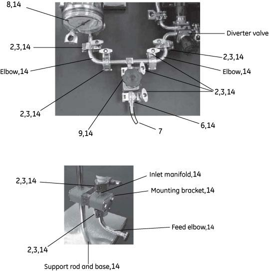
Please note that the numbers are not necessarily in sequential order.
Pressure gauge assembly (part of Adaptor kit 56-4115-32, item no 14 in the component list) includes pressure gauge with CPM connectors, CPM fitting, CPM O-ring and Clamp 50 mm TC.
| # | Product Name | Product Code | Price | |
|---|---|---|---|---|
| 2 | Gasket o.d. 25 mm i.d 13 mm (0.5 inch) | 56411286 | 11.38 USD |
Add to cart
|
| 3 | Clamp 25 mm TC | 56410665 | 161.46 USD |
Add to cart
|
| 6 | 25 mm TC i.d.13 mm (0.5") - 9.5 mm (0.375") Hose Barb | 56411397 | 117.99 USD |
Add to cart
|
| 7 | Peristaltic Tubing, size 18, 3.1 m, i.d. 9.5 mm, bioprene | 56410619 | 171.81 USD |
Add to cart
|
| 9 | Diaphragm Valve 25 mm (0.5") TC Connections, stainless steel | 56411295 | 1,169.00 USD |
Add to cart
|
| Clamp 50 mm TC | 56410667 | 117.99 USD |
Add to cart
|
|
| Gasket 25 mm (0.5") TC i.d. 13 mm, silicone | 56410994 | 78.66 USD |
Add to cart
|
|
| Gasket 25 mm (0.75") TC i.d. 19 mm, silicone | 56410995 | 78.66 USD |
Add to cart
|
|
| Gasket 50 mm (1.5") TC i.d. 38 mm, silicone | 56410996 | 92.12 USD |
Add to cart
|
|
| CPM O-Ring | 56411389 | 162.49 USD |
Add to cart
|
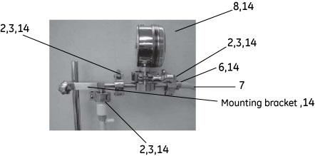
Please note that the numbers are not necessarily in sequential order.
Pressure gauge assembly (part of Adaptor kit 56-4115-32, item no 14 in the component list) includes pressure gauge with CPM connectors, CPM fitting, CPM O-ring and Clamp 50 mm TC.
| # | Product Name | Product Code | Price | |
|---|---|---|---|---|
| 2 | Gasket o.d. 25 mm i.d 13 mm (0.5 inch) | 56411286 | 11.38 USD |
Add to cart
|
| 3 | Clamp 25 mm TC | 56410665 | 161.46 USD |
Add to cart
|
| 6 | 25 mm TC i.d.13 mm (0.5") - 9.5 mm (0.375") Hose Barb | 56411397 | 117.99 USD |
Add to cart
|
| 7 | Peristaltic Tubing, size 18, 3.1 m, i.d. 9.5 mm, bioprene | 56410619 | 171.81 USD |
Add to cart
|
| Peristaltic Pump P-1 | 18111091 | 3,793.00 USD |
Add to cart
|
|
| Clamp 50 mm TC | 56410667 | 117.99 USD |
Add to cart
|
|
| Gasket 25 mm (0.75") TC i.d. 19 mm, silicone | 56410995 | 78.66 USD |
Add to cart
|
|
| Kvick Lab Pressure Gauge Kit, 0–4 bar | 56411369 | 5,307.00 USD |
Add to cart
|
|
| CPM O-Ring | 56411389 | 162.49 USD |
Add to cart
|
The use of a permeate flow control is strongly recommended during upstream clarification of target material. A permeate control valve or a permeate flow control kit together with a pump for the flow rate is required for permeate flow control. Permeate flow control rate is dependent on the process flux (LMH) and surface area.
Detailed information about Permeate control valve (56-4105-88) and Permeate flow control kit (56-4107-73), is available below.
Suitable peristaltic pump for permeate flow control:
Flow rates 0.01 ml/min - 8.3 ml/min (18-1110-91). Permeate tubing i.d. 3.1 mm is suitable for the recommended pump.
Flow rates 5.4 ml/min - 2 liter/min (56-4106-53)
Countries using 220 V power, have to order power cords separately for the pump, model no PRP-09WM, code no 56-4106-53 and system.
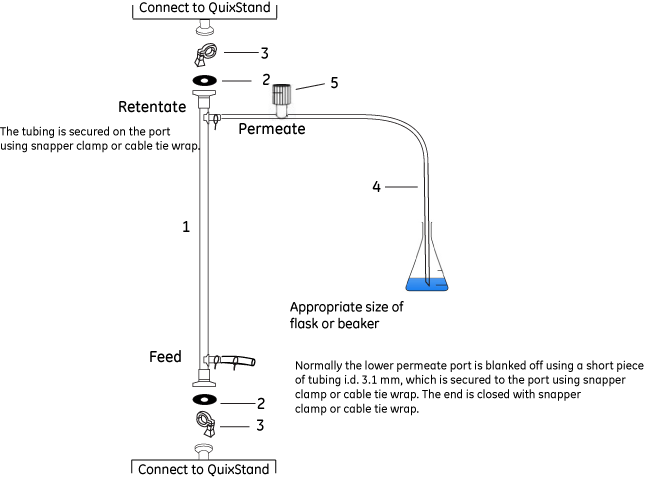
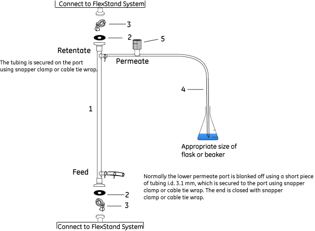
After use, store the cartridge with liquid inside using blank off cap, gasket and clamp on the feed and retentate ports.
Seal the permeate port with a short piece of tubing i.d. 3.1 mm, which is secured using cable tie wrap. The end is closed with snapper clamp or cable tie wrap.
| # | Product Name | Product Code | Price | |
|---|---|---|---|---|
| 2 | Gasket 25 mm (0.5") TC i.d. 13 mm, silicone | 56410994 | 78.66 USD |
Add to cart
|
| 3 | Clamp 25 mm TC | 56410665 | 161.46 USD |
Add to cart
|
| 3 | Clamp 25 mm TC | 56410666 | 115.92 USD |
Add to cart
|
| 4 | Peristaltic Tubing, size 16, 3.1 m, i.d. 3.1 mm, silicone | 56410617 | 134.55 USD |
Add to cart
|
| 5 | Tubing Valve for Tubing o.d. 6.4 mm | 56410588 | 42.43 USD |
Add to cart
|
| Peristaltic Pump P-1 | 18111091 | 3,793.00 USD |
Add to cart
|
|
| Manual Permeate Control Kit, includes vacuum/pressure gauge, backpressure valve, supports, adapters, clamps, and gaskets | 56410773 | 2,222.00 USD |
Add to cart
|
|
| 25 mm (0.5") TC Blank-Off Cap, polysulfone | 56410989 | 61.06 USD |
Add to cart
|
The use of a permeate flow control is strongly recommended during upstream clarification of target material.
The use of a permeate flow control is strongly recommended during upstream clarification of target material. A permeate control valve or a permeate flow control kit together with a pump for the flow rate is required for permeate flow control. Permeate flow control rate is dependent on the process flux (LMH) and surface area.
Detailed information about Permeate control valve (56-4105-88 and 56-4105-89) and Permeate flow control kit (56-4107-73), is available below.
Suitable peristaltic pump for permeate flow control:
Flow rates 0.01 ml/min - 8.3 ml/min (18-1110-91). Permeate tubing i.d. 3.1 mm is suitable for the recommended pump.
Flow rates 5.4 ml/min - 2 liter/min (56-4106-53)
Countries using 220 V power, have to order power cords separately for the pump, model no PRP-09WM, code no 56-4106-53.
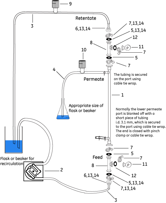
After use, store the cartridge with liquid inside using blank off cap, gasket and clamp on the feed and retentate ports.
Seal the permeate port with a short piece of tubing i.d. 3.1 mm, which is secured using cable tie wrap. The end is closed with pinch clamp or cable tie wrap.
| # | Product Name | Product Code | Price | |
|---|---|---|---|---|
| 3 | Peristaltic Tubing, size 16, 3.1 m, i.d. 3.1 mm, silicone | 56410617 | 134.55 USD |
Add to cart
|
| 3 | Peristaltic Tubing, size 17, 3.1 m, i.d. 6.4 mm, bioprene | 56410618 | 153.18 USD |
Add to cart
|
| 4 | Peristaltic Tubing, size 16, 3.1 m, i.d. 3.1 mm, silicone | 56410617 | 134.55 USD |
Add to cart
|
| 5 | Gasket 25 mm (0.5") TC i.d. 13 mm, silicone | 56410994 | 78.66 USD |
Add to cart
|
| 6 | 25 mm TC 6.4 mm (0.25") Barb | 56410979 | 132.48 USD |
Add to cart
|
| 6 | 25 mm (0.5") TC 9.5 mm (0.375") Barb | 56410980 | 132.48 USD |
Add to cart
|
| 7 | Clamp 25 mm TC | 56410666 | 115.92 USD |
Add to cart
|
| 9 | Tubing Valve for Tubing o.d. 9.5 mm–13 mm | 56410589 | 77.62 USD |
Add to cart
|
| 10 | Tubing Valve for Tubing o.d. 6.4 mm | 56410588 | 42.43 USD |
Add to cart
|
| 11 | Pressure Gauge 0-2 barg (0-30 psig) 25 mm (0.75") TC, side mount | 56410600 | 1,398.00 USD |
Add to cart
|
| 12 | Gasket 25 mm (0.75") TC i.d. 19 mm, silicone | 56410995 | 78.66 USD |
Add to cart
|
| 13 | Connector Kit to Connect 25 mm (1/2") TC to Tubing i.d. 3.1 mm | 56410916 | 320.00 USD |
Add to cart
|
| 14 | Connector Kit to Connect 25 mm TC to Tubing i.d. 6.4 mm | 56410730 | 321.00 USD |
Add to cart
|
| Peristaltic Pump P-1 | 18111091 | 3,793.00 USD |
Add to cart
|
|
| Manual Permeate Control Kit, includes vacuum/pressure gauge, backpressure valve, supports, adapters, clamps, and gaskets | 56410773 | 2,222.00 USD |
Add to cart
|
|
| 25 mm (0.5") TC Blank-Off Cap, polysulfone | 56410989 | 61.06 USD |
Add to cart
|
When running FlexStand Holder with peristaltic pump, the maximum pressure that can be achieved is 2 bar g (30 psi g).
The use of a permeate flow control is strongly recommended during upstream clarification of target material.
A permeate flow control kit together with a pump for the flow rate is required for permeate flow control. Permeate flow control rate is dependent on the process flux (LMH) and surface area. Detailed information about Permeate control valve (56-4105-88) and Permeate flow control kit (56-4107-73), is available below.
Suitable peristaltic pump for permeate flow control:
Flow rates 0.01 ml/min - 8.3 ml/min (18-1110-91). Permeate tubing i.d. 3.1 mm is suitable for the recommended pump.
Flow rates 5.4 ml/min - 2 liter/min (56-4106-53)
Feed pump (56-4106-53), Feed reservoir (56-4107-67), Outlet pressure gauge for FS-03LVS (56-4106-04), Outlet pressure gauge for FS-03LVS-30 ( 56-4106-03) and Tubing (56-4106-17) have to be ordered separately.
For countries using 220 V power, power cords have to be ordered separately for the pump, model no PRP-09WM, code no 56-4106-53.

After use, store the cartridge with liquid inside using blank off cap, gasket and clamp on the feed and retentate ports. Seal the permeate port with a short piece of tubing i.d. 3.1 mm, which is secured using cable tie wrap. The end is closed with snapper clamp or cable tie wrap.
| # | Product Name | Product Code | Price | |
|---|---|---|---|---|
| 2 | Gasket 25 mm (0.5") TC i.d. 13 mm, silicone | 56410994 | 78.66 USD |
Add to cart
|
| 3 | Clamp 25 mm TC | 56410665 | 161.46 USD |
Add to cart
|
| 4 | Peristaltic Tubing, size 16, 3.1 m, i.d. 3.1 mm, silicone | 56410617 | 134.55 USD |
Add to cart
|
| 5 | Tubing Valve for Tubing o.d. 6.4 mm | 56410588 | 42.43 USD |
Add to cart
|
| Peristaltic Pump P-1 | 18111091 | 3,793.00 USD |
Add to cart
|
|
| Peristaltic Tubing, size 17, 3.1 m, i.d. 6.4 mm, bioprene | 56410618 | 153.18 USD |
Add to cart
|
|
| Clamp 25 mm TC | 56410666 | 115.92 USD |
Add to cart
|
|
| Clamp 64 mm (2") TC | 56410670 | 87.98 USD |
Add to cart
|
|
| Manual Permeate Control Kit, includes vacuum/pressure gauge, backpressure valve, supports, adapters, clamps, and gaskets | 56410773 | 2,222.00 USD |
Add to cart
|
|
| 25 mm (0.5") TC Blank-Off Cap, polysulfone | 56410989 | 61.06 USD |
Add to cart
|
|
| Gasket 64 mm (2") TC i.d. 50 mm, silicone | 56410998 | 108.68 USD |
Add to cart
|
The use of a permeate flow control is strongly recommended during upstream clarification of target material.
A permeate flow control kit together with a pump for the flow rate is required for permeate flow control. Permeate flow control rate is dependent on the process flux (LMH) and surface area. Detailed information about Permeate control valve (56-4105-88) and Permeate flow control kit (56-4107-73), is available below.
Suitable peristaltic pump for permeate flow control:
Flow rates 0.01 ml/min - 8.3 ml/min (18-1110-91). Permeate tubing i.d. 3.1 mm is suitable for the recommended pump.
Flow rates 5.4 ml/min - 2 liter/min (56-4106-53)
Feed reservoir (56-4107-67 or 56-4107-70) has to be ordered separately. Detailed information can be found below.
For countries using 220 V power, power cords have to be ordered separately for the pump, model no PRP-09WM, code no 56-4106-53.
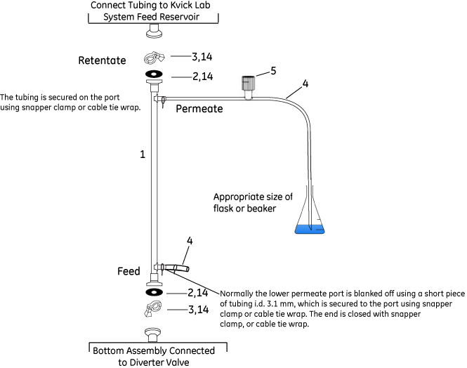
After use, store the cartridge with liquid inside using blank off cap, gasket and clamp on the feed and retentate ports. Seal the permeate port with a short piece of tubing i.d. 3.1 mm, which is secured using cable tie wrap. The end is closed with snapper clamp or cable tie wrap.
| # | Product Name | Product Code | Price | |
|---|---|---|---|---|
| 2 | Gasket 25 mm (0.5") TC i.d. 13 mm, silicone | 56410994 | 78.66 USD |
Add to cart
|
| 3 | Clamp 25 mm TC | 56410665 | 161.46 USD |
Add to cart
|
| 4 | Peristaltic Tubing, size 16, 3.1 m, i.d. 3.1 mm, silicone | 56410617 | 134.55 USD |
Add to cart
|
| 5 | Tubing Valve for Tubing o.d. 6.4 mm | 56410588 | 42.43 USD |
Add to cart
|
| Peristaltic Pump P-1 | 18111091 | 3,793.00 USD |
Add to cart
|
|
| Clamp 25 mm TC | 56410666 | 115.92 USD |
Add to cart
|
|
| Clamp 64 mm (2") TC | 56410670 | 87.98 USD |
Add to cart
|
|
| Manual Permeate Control Kit, includes vacuum/pressure gauge, backpressure valve, supports, adapters, clamps, and gaskets | 56410773 | 2,222.00 USD |
Add to cart
|
|
| 25 mm (0.5") TC Blank-Off Cap, polysulfone | 56410989 | 61.06 USD |
Add to cart
|
|
| Gasket 64 mm (2") TC i.d. 50 mm, silicone | 56410998 | 108.68 USD |
Add to cart
|
The use of a permeate flow control is strongly recommended during upstream clarification of target material.
A permeate control valve together with a pump for the flow rate is required for permeate flow control. Permeate flow control rate is dependent on the process flux (LMH) and surface area. Detailed information about Permeate control valve (56-4105-88), is available below.
Suitable peristaltic pump for permeate flow control:
Flow rates 0.01 ml/min - 8.3 ml/min (18-1110-91). Permeate tubing i.d. 3.1 mm is suitable for the recommended pump.
Flow rates 5.4 ml/min - 2 liter/min (56-4106-53)
For countries using 220 V power, power cords have to be ordered separately for the pump, model no PRP-09WM, code no 56-4106-53.
After use, store the cartridge with liquid inside using blank off cap, gasket and clamp on the feed and retentate ports.
Seal the permeate port with a short piece of tubing i.d. 3.1 mm, which is secured using cable tie wrap. The end is closed with snapper clamp or cable tie wrap.
| # | Product Name | Product Code | Price | |
|---|---|---|---|---|
| 2 | Gasket o.d. 25 mm i.d 13 mm (0.5 inch) | 56411286 | 11.38 USD |
Add to cart
|
| 3 | Clamp 25 mm TC | 56410665 | 161.46 USD |
Add to cart
|
| 4 | Peristaltic Tubing, size 16, 3.1 m, i.d. 3.1 mm, silicone | 56410617 | 134.55 USD |
Add to cart
|
| 5 | Tubing Valve for Tubing o.d. 6.4 mm | 56410588 | 42.43 USD |
Add to cart
|
| 7 | Peristaltic Tubing, size 18, 3.1 m, i.d. 9.5 mm, bioprene | 56410619 | 171.81 USD |
Add to cart
|
| Peristaltic Pump P-1 | 18111091 | 3,793.00 USD |
Add to cart
|
|
| 25 mm (0.5") TC Blank-Off Cap, polysulfone | 56410989 | 61.06 USD |
Add to cart
|