Based upon years of filtration expertise, this article details extensive guidance for wetting filters to enable successful pre- and post-use integrity testing.
- When to integrity test a filter and the choice of wetting fluid
- Important points to consider for successful complete wetting of a filter
- Wetting recommendations for different applications and cases
- Pre-use post sterilization integrity test (PUPSIT)–stainless steel systems and other non-volume restricted systems
- Wetting recommendations for hydrophobic filters
- Wetting recommendation for hydrophilic filters when wetted with IPA/water
- Recommended setup and steps for wetting in stainless steel systems and other non-volume restricted systems
- What to do in the event of a pre-use or post-sterilization IT failure
- Low-wetting volume integrity testing typically used in single-use systems
- Enhanced wetting for single use or stainless-steel applications
- Post-use integrity testing
- Procedure in the event of post-use IT failures
Why integrity test filters?
Microbially-rated membrane filter cartridges and capsules are widely used throughout the biotechnology and pharmaceutical industries for bioburden reduction, fluid sterilization, as well as mycoplasma clearance. Integrity testing of these filters, either out-of-box, after sterilization/pre-filtration (both can be referred to as “pre-use”), and/or post filtration, is required in many applications.
Integrity testing (IT) of sterilizing-grade filters is necessary to reliably detect damage to these sterile barriers which would compromise the sterility and patient safety of biopharmaceuticals. Although an integrity test is part of quality release for filter manufacturers, testing at point-of-use is strongly recommended as every filter is subjected to transport, storage and handling by an end user as part of its journey after it has left the manufacturing facility. So, ensuring filter integrity, particularly for critical use applications, is paramount.
Regulatory authorities request a suitable integrity test of critical sterilizing grade filters after use (post-use) or just before use, after sterilization. This last type of integrity test, known as PUPSIT (pre-use post sterilization integrity test) is part of compliance testing required by EU-GMP Annex I.
Integrity testing of membrane filter cartridges and capsules by forward flow (diffusion) or bubble point-type tests requires complete wetting of the membrane such that all flow pathways are filled with the wetting liquid (water, buffer, product, etc.). Thorough wetting allows the integrity test to be appropriately conducted and avoids false failures which can occur due to incomplete wetting, where air can freely flow through non-wetted or incompletely-wetted pathways.
Flushing of filters pre-use is recommended to reduce the presence of particles downstream of the filter assembly and to reduce leachables from the filter. Flushing to reduce leachables should be carried out post-sterilization, as the sterilization process typically stimulates formation of leachables. The amount and composition of filter leachables after flushing will vary depending on the membrane type and the method of sterilization.
When to integrity test a filter and the choice of wetting fluid
The rules and recommendations on whether filters have to be tested pre-use or post-use are not aligned between the different regulatory authorities. FDA and EU GMP guidelines both state that a post-use integrity test must be performed. Both the FDA and EU GMP guidelines emphasize the importance of pre-use testing. Whilst the FDA GMP guidelines only recommend a pre-use test, the EU GMP guidelines require that filters are tested after sterilization, and before they are used. The technology to perform a pre-use post-sterilization filter integrity test is available and can be implemented without great effort in many cases. While PUPSIT has been required by Annex 1 for many years, the most recent revision has allowed for exclusions based on an acceptable risk assessment. However, industry trends suggest that PUPSIT enforcement by European authorities is increasing, as submitted risk assessments have not been robust enough or are not based on the potential risk to the patient.
The most common liquids used to wet the filter for the integrity test are:
- Water
- A mixture of water with alcohol
- The product to be filtered
- A buffer the product is dissolved in
In many pharmaceutical processes, alcohol is not compatible with the pharmaceutical ingredient and therefore not suitable for inline tests. It is mostly used for post-use-IT, as a backup in case of IT failures on hydrophilic membranes, or for wetting of hydrophobic filter membranes.
For hydrophilic filters, water, buffer or product can be used to wet the filter for the pre-use test. With each different wetting agent, a number of points are worth considering to ensure it is the most suitable for the pre-use test in a specific process (see Table 1).
Table 1. Guidance for choosing a wetting liquid for PUPSIT of liquid filters
| Point to consider | Water | Buffer | Product | Product with extractable flush |
| Integrity test parameters | Standard supplier package | Need for product specific validation study | Need for product specific validation study | Need for product specific validation study |
| Product exposure before/during PUPSIT | Product is exposed to filter / SUS only if PUPSIT pass result | Product is exposed to filter / SUS only if PUPSIT pass result | Need risk assessment for bioburden penetration | Need risk assessment for bioburden penetration |
| Risk of flaw masking | WFI is not plugging | Buffer is not plugging | Low risk if product prefiltered on 0.2 µm | Low risk if product prefiltered on 0.2 µm |
| Product dilution in first filled containers or vials / Elimination of water residues | Water displacement by the product (need flush study). High volumes of discarded product | Buffer displacement by the product (need flush study). Low volumes of discarded product | No product dilution | No product dilution |
| Complexity (SUS design and operation) | Need water inlet and a flush biocontainer | Need buffer inlet and a flush biocontainer | No water inlet and flush biocontainer unless flush for extractables and leachables reduction is needed | Need extractable flush biocontainer |
| Recommended volumes for complete wetting before PUPSIT | Water is a well-known reference wetting fluid with guidance available for different filter types | Product characteristics may challenge the wetting | Product characteristics may challenge the wetting | Product characteristics may challenge the wetting |
| Wetting volume cost impact | Wetting volume not limited to cost | Wetting volume not limited to cost | Wetting volume is not lost | Limited volume due to its cost. Depending on product cost. |
| Wettability of filter membrane | Recommendations available. Most filter membranes can be well wetted with water | Certain buffers with high salt or high sugar concentrations may not be suitable for filter wetting | Certain products with high salt or high sugar concentrations may not be suitable for filter wetting | Certain products with high salt or high sugar concentrations may not be suitable for filter wetting |
| Post-use IT in-situ | Would require determination of parameters to flush product from membrane. Typically, larger flush volumes required depending on the complexity of the product | Would require determination of specific parameters for IT. Typically, larger flush volumes required depending on the complexity of the product | Post-use IT parameters with product determined to allow point-of-use post-use IT without further flushing (and qualification of flushing) | Post-use IT parameters with product determined to allow point-of-use post-use IT without further flushing (and qualification of flushing) |
For pre-use testing, when using water or buffer as wetting liquid, especially in single use designs, there are often requirements to have as little wetting fluid as possible on the downstream side of the filter due to restrictions in the volume of the sterile waste receiver. From a space saving point of view, the size of this receiver cannot be too large. In single-use systems the flush biocontainer should have a size that is adequate for the filter size and system configuration. Large flush biocontainers (e.g., 3D) may not be installed for rather small filtration systems (e.g., capsules with less than 2000 cm2 filtration area).
When the wetting liquid is directed to the product vessel, to a surge bag or in final filling applications, dilution of the product must be kept to a minimum. The residual liquid in the filter, or the line downstream of the filter, should then either be calculated into the dilution of the product or the filter system should be flushed with an amount of product to assure the correct product concentration.
When considering product as a wetting liquid, suitability of its ability to sufficiently wet out the filter membrane has to be assessed. Some products may not be suitable to wet out a filter membrane properly under the wetting conditions that can be applied in a certain setup. It is common for a more vigorous wetting regime to be required to fully wet a membrane and in these instances the process setup needs to allow for that. In some rare cases, wetting may not be possible at all (e.g., high-sugar or high-salt concentrations).
For post-use integrity testing, either product or water are the first choice wetting liquid. When using water, an appropriate amount must be flushed through the filter to avoid the presence of product residues. Alcohol-water mixtures may be used if the filter is intended to be tested with water but removal of product from the filter is not efficient enough using water alone. This is important because product residues on a filter can lead to elevated gas flows during IT and subsequently lead to false failures.
To be tested by forward flow or a bubble point-type of test, hydrophobic filters need to be wetted with a suitable alcohol-water mixture for pre-use and post-use testing. For post-use testing more extended flushing may be necessary than for pre-use testing, as potential product residues on the membrane may have to be removed (e.g., air filters on bioreactors).
Important points to consider for successful complete wetting of a filter
As forward flow (FF) or bubble point (BP)-type tests can only be successfully carried out with a meaningful result on a completely wetted filter membrane, applying a suitable wetting regime is crucial.
Venting and filter orientation
The most crucial aspect of wetting a filter cartridge is to fully remove the air out of the filter construction (the venting step) to enable the wetting fluid to reach all parts of the membrane. The most critical point here is the potential for air to be entrapped at the top end of the inner core of the filter element, which can prevent proper wetting of the filter membrane. For optimal wetting, filter cartridges should be installed in an ‘upright’ configuration with the filter outlet at the bottom.
Although it may be favorable for venting the core, installations with the filter outlet on top should be avoided because:
- Product cannot be fully recovered through the sterilizing grade filter; a complete ’housing volume of product’ can be lost for such an installation.
- Steam sterilization (where applicable) could be compromised with a filter installed upside down, as water can become trapped in the inner core of the filter cartridge.
Horizontal or tilted setups are sometimes needed because of space restrictions. However, these setups often require venting from the filter vent valve to a biocontainer (via tubing) or makes use of an additional vent filter. This degree of complexity increases the risk of potential leak points. Especially for redundant filtration, as the vent valve is on the upstream side of the filter; this risk increases even more as venting of the second filter takes place downstream of the first one. The main advantage of vertical orientation is that it allows for better draining of the product. It also aids automated operations as vents on the filter housing do not have to be actuated.
To allow for sufficient venting in a setup where venting does not take place over the vent valve but at the top of the filter (for example PUPSIT shadow boards), a certain diameter of the filter inlet is necessary. Figure 1 shows how air escapes in this case and illustrates why filter inlets with very small inner diameter are not recommended.
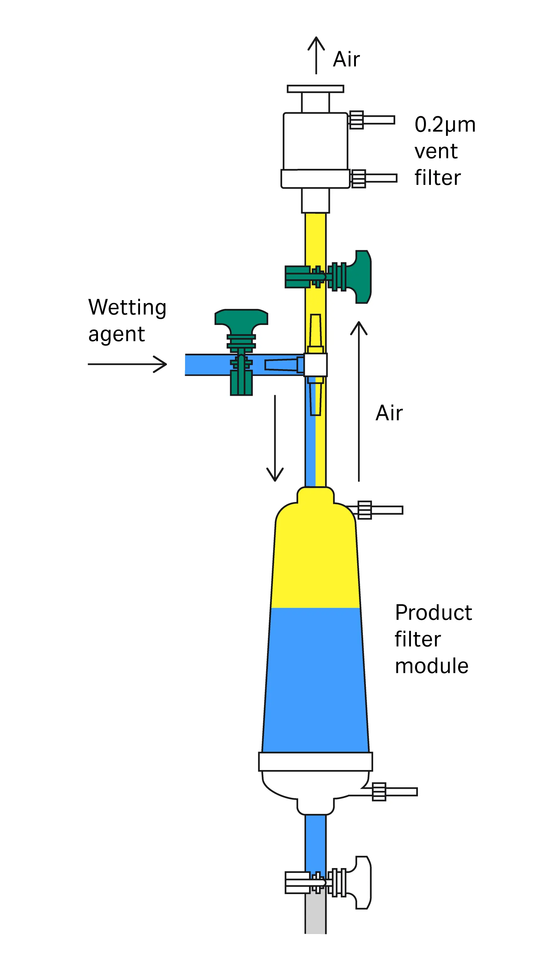
Fig 1. Illustration of vertical filter venting.
Filters with a stepped hose barb ¼”-⅜” for example, have an internal diameter that is too low and should not be incorporated in single-use systems where PUPSIT is required. This is because the internal diameter will not allow for the simultaneous actions of air escaping and liquid flowing downwards, during venting.
Importance of low flows during venting/priming
Initially, slow filling of the filter capsule/housing is crucial. This helps to expel as much air as possible from the installation and avoids splashing that may lead to punctual wetting of the membrane and subsequent preferred flow through those spots during wetting. To reach the required low flows during venting, a peristaltic pump is generally required.
Factors influencing filter wetting
Optimizing the following parameters will improve filter wetting:
- Wetting fluid contact time (e.g., with a soaking step)
- Flow rate
- Back pressure
Back pressure is achieved by placing a restriction on the outlet of the filter assembly during forward flushing. This can be achieved by using a valve, smaller piping size, tubing clamp, or similar constriction, maintaining a pressure differential from upstream to downstream. Note, that back pressure is not reverse pressure. The use of back pressure during flushing helps to ensure uniform flow distribution through the filter, i.e., it helps overcome the fluid tendency to flow through the ‘path of least resistance’, i.e., larger flow pathways. Back pressure also facilitates the removal of air entrapped in the membrane pleats by further solubilizing the air by increased system pressure and by compressing air bubbles to a size where they may pass through the membrane.
Wetting recommendations for different applications and cases
Wetting regimes applicable to a certain filter type do not only depend on the filter`s characteristics, but also on the process setup and process conditions where the filter is used.
Our recommendations given here detail different conditions required for different setups. It should be noted that a recommended wetting regime for a particular filter is dependent on where it is located within the process.
Typically, in single-use setups there are restrictions regarding the volume a filter can be flushed with or the pressures that can be applied for the flushing, whereas in a stainless steel production environment there are less limitations.
For pre-use integrity testing the most important point is complete wetting of the filter membrane. However, for post-use testing, if carried out with water and not with product, flushing to allow complete removal of product from the filter membrane is crucial. Therefore, the focus for post-use testing is on flush volume and other measures such as soaking, fostering removal of product residues from the filter membrane.
Pre-use post sterilization integrity test (PUPSIT) for stainless steel systems and other non-volume restricted systems
Our general recommendations for filter wetting with water for the purpose of pre-use integrity testing, in cases where there are no restrictions regarding flush volume, are:
For 0.2 µm microbially-rated liquid service filters:
4 to 8 L/min per 254 mm (10 in.) filter for 10 minutes
For 0.1 µm microbially-rated liquid service filters:
2 to 4 L/min per 254 mm (10 in.) filter for 10 minutes
Table 2 shows the recommended flow rates of 4 to 8 L/min and 2 to 4 L/min for 0.2 µm and 0.1 µm microbially-rated 254 mm (10 in.) filters converted for smaller filters sizes.
Table 2. Water and IPA/water flow rates for various filter sizes to achieve complete wetting
| Filter style description | Associated product code prefix | Typical filtration area | Water wetting flow rate for 0.2 µm filters* |
Water wetting flow rate for 0.1 µm filters and IPA/water flow rates for hydrophobic and hydrophilic filters |
| Mini Kleenpak™ syringe filter capsules | KM2 | 2.8 cm2 | 3 mL/min | 1 mL/min |
| Mini Kleenpak™ 20 capsules | KM5 | 20 cm2 | 10 mL/min | 5 mL/min |
| Mini Kleenpak™ capsules | KA02 | 200–220 cm2 | 125 mL/min | 60 mL/min |
| Kleenpak™ capsules, junior cartridges or Novasip™ capsules | KA1 / MCY1110 / CL1 | 375–500 cm2 | 250 mL/min | 125 mL/min |
| Kleenpak™ capsules, junior cartridges or Novasip™ capsules | KA2 / MCY2220/ MCY 3330 / C(L)2 | 750–1200 cm2 | 500 mL/min | 250 mL/min |
| Kleenpak™ capsules, junior cartridges or Novasip™ capsules | KA3 / MCY4440 / MCY4463 / C(L)3 | 1500–2000 cm2 | 1 L/min | 500 mL/min |
| Kleenpak™ capsules | KA4 | 3300–5000 cm2 | 2 L/min | 1 L/min |
| 125 mm (5 in.) Kleenpak™ Nova capsule or AB-style cartridge | NP5 / AB05 | 0.27–0.55 m2 | 2–4 L/min | 1–2 L/min |
| 254 mm (10 in). Kleenpak™ Nova capsule or AB-style cartridge | NP6 / NT6 / AB1 | 0.55–1.1 m2 | 4–8 L/min | 2–4 L/min |
| 508 mm (20 in.) Kleenpak™ Nova capsule or AB-style cartridge | NP7 / NT7 / AB2 | 1.1–2.2 m2 | 8–16 L/min | 4–8 L/min |
| 762 mm (30 in.) Kleenpak™ Nova capsule or AB-style cartridge | NP8 / NT8 / AB3 | 1.6–3.3 m2 | 12–24 L/min | 6–12 L/min |
*Filling rate for venting should not exceed 150 ml/min per 10 in. element. For filters with smaller effective filtration areas filling flow rates have to be adapted accordingly.
Wetting recommendations for hydrophobic filters
For hydrophobic filters that are not testable by WIT, PUPSIT does not apply. These filters are wetted with a low surface tension wetting liquid in order to carry out a forward flow test or bubble point test and have to be dried before they can be used in the process.
For hydrophobic filters that require pre-use testing we recommend wetting with alcohol-water mixtures (half the liquid filter flow rates are typically sufficient, see Table 2).
Wetting recommendation for hydrophilic filters when wetted with IPA/water
For hydrophilic filters, when wetted with IPA/water mixtures, the same flow rates are sufficient as for hydrophobic filters (see Table 2).
Recommended setup and procedure for wetting in stainless steel systems and other non-volume restricted systems
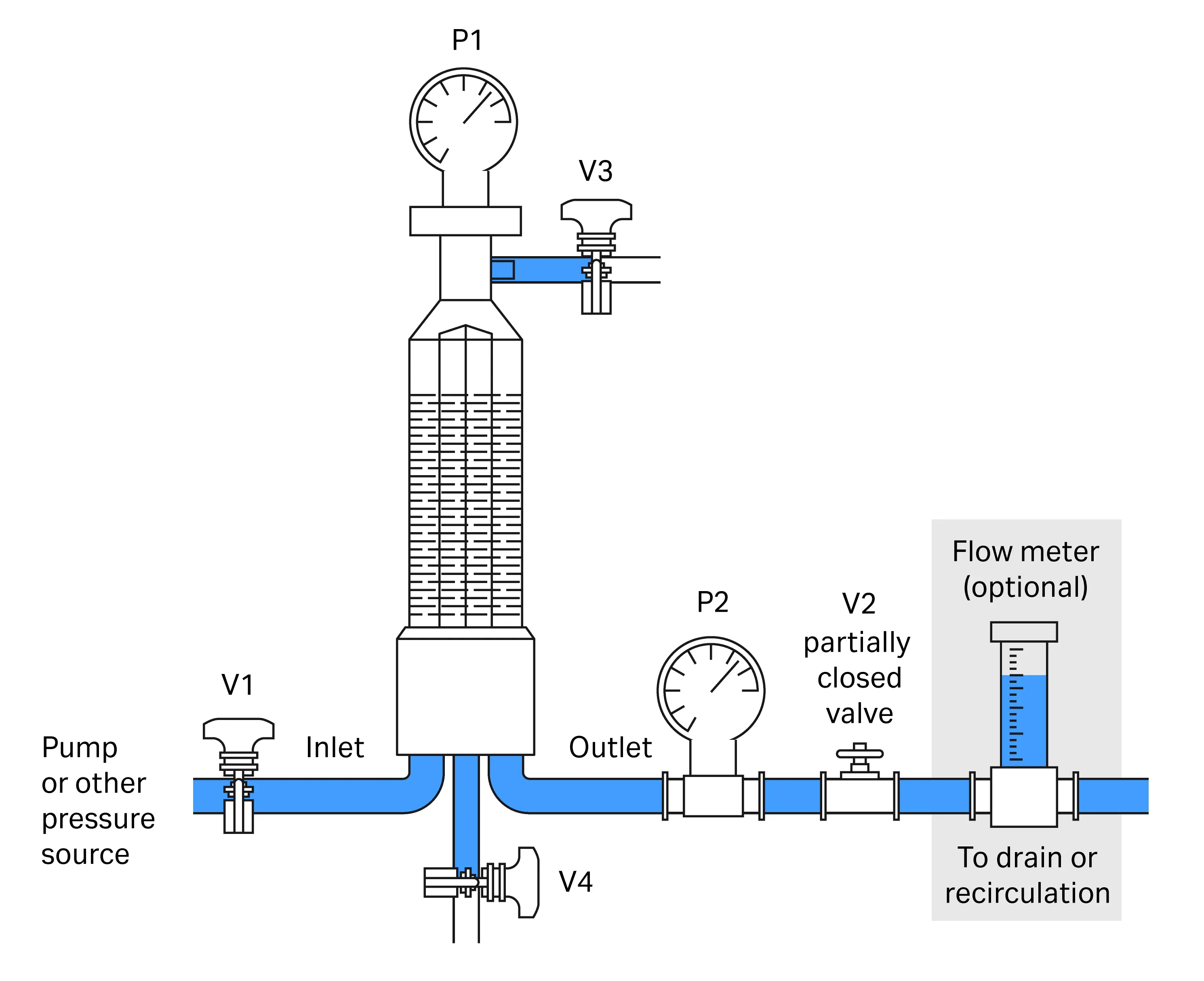
Fig 2. Flushing procedure–set up for flushing, applying back pressure.
- Start with all valves closed. Open inlet V1, and vent V3 valves.
- Start pump/open pressure source slowly (to allow not more than 150 mL/min flow per 10” filter) and bleed all air from the assembly through V3. When trapped air is no longer seen, close V3. Note: If flushing a capsule filter or using an in-line filter cartridge housing, ensure that the vent is located at the highest point during this venting phase.
- After venting and closing V3, build up pressure upstream on gauge P1 and open outlet valve V2 progressively until a backpressure of > 1 barg (15 psig/0.1 MPag) is indicated on the downstream pressure gauge P2.
- Check flow rate for the appropriate flow (refer to Table 2). Adjust V1 or pressure source as necessary.
- Adjust V2 to maintain the flow/pressure and back pressure conditions. A flow rate and back pressure higher than recommended is acceptable.
- Flush for the desired time.
- Stop pump or release pressure source and allow system to depressurize without manipulation of any valves.
- Drain system by opening V4, then V3.
- Close V1, V3, V4. Fully open V2 (and V3 if integrity test instrument is connected via this valve).
- Perform integrity test.
What to do in the event of a pre-use or post-sterilization IT failure
In the event of integrity test failures, as indicated in PDA TR26, we recommend following a Standard Operation Procedure (SOP), typically involving these steps:
- Checking the system for leaks.
- Re-wetting with enhanced flush conditions (extending flush time, increasing back pressure, increasing flow rate; or all three of these parameters).
- Reiterate step 2. Each new iteration should have at least one parameter enhanced compared to the previous test.
- Rejecting a filter that is still unable to achieve a pass after the first three steps and returning to the supplier for investigation.
Low-wetting volume integrity testing typically used with single-use systems
This procedure is used when it is only possible to flush with low volumes of wetting fluid. A typical example is when using single-use assemblies where the volume is restricted.
The following steps describe filter wetting in single use assemblies (see Fig 3).

Fig 3. Example for setup for in-line configuration single use format.
- Start with all valves closed.
- Open V1 and V2.
- Start the pump at a low speed (see Table 3 for recommended flow rates for filling the filter capsule/housing) or throttle V1 for systems that are pressure driven.
- Visually monitor the filling of product filter capsule.
- Allow filling to continue until upstream volume of product filter is full and free from air.
- Stop the pump (or close pressure source) and close V2 when liquid level is reaching the T-piece between V1 and V2. Attention must be taken to ensure liquid does not contact the vent filter.
- After complete filling of the housing using recommended filling flow (refer to Table 3), open V3 (if possible, only partially to allow for back pressure) or any relevant valve going to waste.
- Start pump (or open pressure source) and increase pump speed (or adjust V1) to achieve defined wetting flow rate and flush with the recommended volume (refer to Table 3).
- Stop the pump (close pressure source), close V1 and fully open V2 and V3.
- Perform integrity test.

|
|
|


A pressure sensor downstream of the filter is recommended to control the downstream pressure during the wetting procedure and/or during the integrity test if the filter outlet is not open to the atmosphere.
If wetting is not reliably achieved using this procedure, if not already applied, work with back pressure and/or, a pressurized soaking step after initial filling. For recommended soaking pressures please refer to Table 3.
Configuration for static soak:

Applying back pressure is recommended to enhance efficiency of wetting, although this may not be possible in all instances and setups.
Enhanced wetting procedure for single use or stainless steel applications
Some products, for example with high salt or high sugar concentrations, due to their ability to attract water, make it more difficult (when compared to water) to properly wet out a filter membrane. In these cases it can be challenging (sometimes impossible) to obtain a completely wetted membrane with the setup and procedure previously described. This is true for applications in single-use systems where pressure and volume is restricted.
The following enhanced procedure for the filling of the filter is suggested with a pressure sensor downstream of the filter to control pressure built up during filling.
Step 1: Filling (and venting)

- Ensure the filter under test is in an upright position.
- The valves at the downstream side and valve V3 (or vent valve V3` of the filter housing) remain closed.
- Open V1. Fill the filter housing slowly with wetting fluid by starting the pump at low speed or adjust V1 to achieve defined wetting flow rate (see Table 3).
- When a pressure of 0.5 to 0.8 bar is reached at the pressure transducer, vent the housing via valve V3 (or vent valve V3` of the filter housing). As soon as the pressure returns to zero, close the vent valve again and continue filling. Pump/pressure keeps running during this step.
Repeat steps 3 and 4, alternately filling and venting, until filter cartridge is completely covered by liquid and close V3 when liquid level is reaching the T-piece between V1 and V3 (attention must be taken to ensure liquid does not contact vent filter) or bubble free liquid comes from the vent valve of the filter (V3`).
Optional pressurized soaking step:
Close V1 and pressurize the filled housing via V3 (or vent valve V3`of the filter housing) with compressed air or nitrogen at 0.8-2 bar for 5 min.
Step 2: Flushing

1. Apply pressure via V3 (or vent valve V3`of the filter housing) and open V4 to flush into product vessel or flush container.
For recommended parameters for filling, pressurizing and flushing see Table 3.
For more challenging situations:
2. After flushing leave V4 open and pressurize the emptied filter housing /capsule via V3 (or vent valve V3`of the filter housing) with integrity test pressure (for forward flow, or 500 mbar below minimum bubble point) for 300 s while having V1 closed. Then continue with step 1 (filling).
Step 3: Perform integrity test

1. Connect the integrity test instrument to the top of the filter housing over the vent filter or V3`. (If the integrity test instrument is connected to V3`, the filter should be drained below V3` before connection of the instrument to avoid contamination of the test device.)
2. Ensure V3 (or V3`) and V4 are fully open.
3. Perform integrity test.
Note:
If neither V4 or V5 can be opened or if a non-vented bag is connected to the open valve, the pressure downstream must be monitored, especially in the initial phase of the pressurization by the integrity test instrument, in order to become aware of the pressure increase which can potentially be due to insufficient wetting or major leaks in the membrane.
If one wetting cycle is not sufficient to obtain a positive test result, adapt the procedure for two cycles. Between the cycles add a 5 min pressure hold step for the drained housing at test pressure. The downstream valve should be open during this phase, the same as for an integrity test.
Table 3. Recommended parameters for wetting/flushing filters in single-use systems and other volume restricted systems with water or other aqueous solutions
| Filter Size | Flow rate for filling during venting [mL /min] |
Water wetting flow [mL/min] |
Recommended minimum flush volume for wetting [L] |
Optional soaking step (filter outlet closed) |
Optional pressurizing step (filter outlet open) |
| KA02 | 10-20 | 50 | 0.100 | 800-2000 mbar for 120-300 s |
Actual test pressure |
| KA1 | 50 | 100 | 0.150 | ||
| KA2 | 100 | 150 | 0.300 | ||
| KA3 | 100 | 300 | 0.6 | ||
| 5 in. / NP5 | 150 | 500 | 1.5 | ||
| 10 in. / NP6 | 150 | 1000 | 3 | ||
| 20 in. / NP7 | 200 | 2000 | 6 | ||
| 30 in. / NP8 | 200 | 2000 | 9 |
Post-use integrity testing
Post-use integrity testing is often done off-line. As a process finishes, in many cases the filter to be tested can be disconnected (for stainless steel applications the filter remains mounted in the housing). For product that is hazardous in nature, an in-situ test while still connected to the line may also be necessary post-use.
For post-use testing, as for pre-use testing, the primary focus is on completely wetting the pores of the filter membrane with the respective wetting liquid. However, while initial wetting of the filter membrane (by reaching the whole membrane area) is the main goal for pre-use testing, for post-use testing, cleaning the membrane from product residues is the objective. During the filtration process, components of the product may have accumulated that may negatively impact the result of the integrity test (false failures) as these substances may prevent proper wetting of the pores of the membrane. In such cases, an adequate flushing regime has to be applied, or a low surface tension liquid may be needed to overcome this condition.
For hydrophilic filters, post-use IT can be performed with product, buffer, water or alcohol/water mixtures. For testing with product, flushing is not needed, however when using other wetting liquids, adequate flushing regimes have to be qualified.
For hydrophobic filters post-use wetting is carried out with a suitable alcohol-water mixture. Actual flushing regimes depend on how the filter was used and if there are any contaminants present on the membrane that need to be removed.
Determination of post-use flushing regimes should be part of the process qualification.
Procedure in the event of post-use IT failures
We refer to PDA TR 26 as a guide for a post-use IT failure procedure/decision tree.
In the event of a post-use IT failure, procedures should focus on cleaning the membrane and/or overcoming any contaminants that lead to changes in surface tension of the membrane, as such we can only provide more detailed recommendations on post-use flushing when we have knowledge of the individual process. Our application specialists can provide specific recommendations for individual processes.
Flushing volume, wetting liquid, adding a static soak step, as well as adapting flushing conditions (such as applying back pressure) are crucial parameters to optimize. Due to the diversity of product being filtered, guidance will need to be adapted to the actual situation.
Conclusion
The procedures outlined in this guidance document are possible approaches to appropriately flush and wet a filter prior to use.
Whether you need to discuss a more customized approach for specific applications based on your individual process, or require wetting recommendations for our Supor™ Prime sterilizing grade filters, designed for high concentration drugs, tap into our filtration experience.
Visit cytiva.com/contact and discover how our application specialists can help.
CY55165